Double-stage compression heat pump circulation system for deeply condensing steam exhaust

A deep condensation and two-stage compression technology, applied in heat pumps, fluid circulation arrangements, refrigerators, etc., can solve the problems of low coefficient of performance and efficiency of heat pumps, low evaporation temperature of heat pumps, poor energy saving, etc.

Pending Publication Date: 2019-03-08
SHANGHAI ENN NEW ENERGY TECH CO LTD
View PDF5 Cites 4 Cited by
  • Summary
  • Abstract
  • Description
  • Claims
  • Application Information

AI Technical Summary

Problems solved by technology

[0004] In order to solve the problems that existing conventional heat pumps are used to recover the condensation heat of the final effect low-pressure exhaust steam of multi-effect evaporation, the existing heat pump evaporation temperature is relatively low, the performance coefficient and efficiency of the heat pump are relatively low, and the energy saving performance is poor, and further proposes a A Two-stage Compression Heat Pump Cycle System for Deep Condensation of Exhaust Steam

Method used


Image

  • Double-stage compression heat pump circulation system for deeply condensing steam exhaust
  • Double-stage compression heat pump circulation system for deeply condensing steam exhaust
  • Double-stage compression heat pump circulation system for deeply condensing steam exhaust

Examples


specific Embodiment approach 1

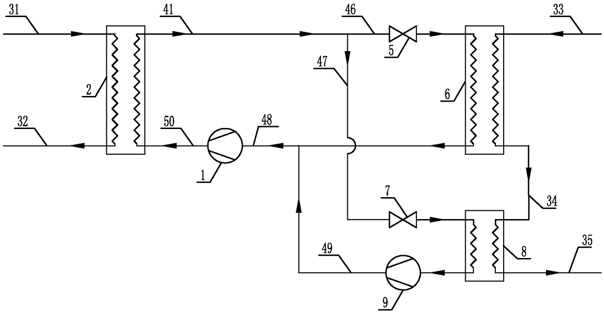
[0051] Specific implementation mode one: combine figure 1 This embodiment is described. A two-stage compression heat pump cycle system for deep condensation of exhaust gas in this embodiment includes a first compressor 1, a heat pump condenser 2, a second throttling expansion valve 5, a heat pump first evaporator 6, The third throttling expansion valve 7, the second evaporator 8 of the heat pump, the second compressor 9, the first heat transfer medium pipeline 31, the second heat transfer medium pipeline 32, the first exhaust steam pipeline 33, the second exhaust steam pipeline Steam pipeline 34, third exhaust steam pipeline 35, first refrigerant pipeline 41, sixth refrigerant pipeline 46, seventh refrigerant pipeline 47, eighth refrigerant pipeline 48, ninth refrigerant pipeline Road 49 and the tenth refrigerant pipeline 50,

[0052] The outlet end of the first heat transfer medium pipeline 31 is connected to the heat medium inlet end of the heat pump condenser 2, and the he...

specific Embodiment approach 2

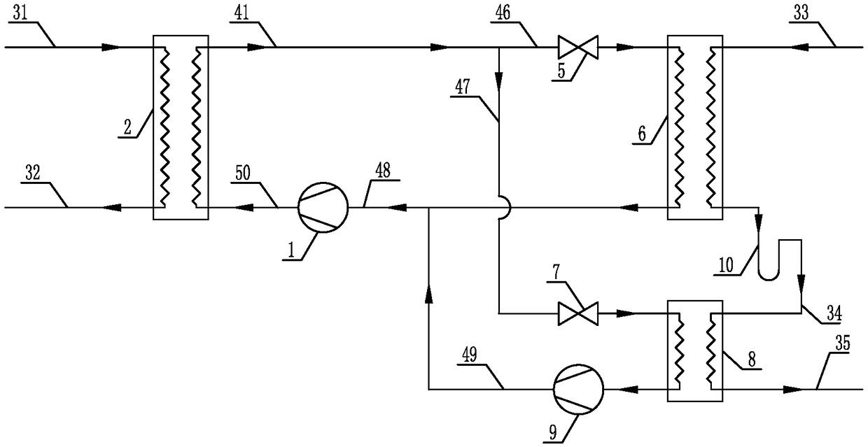
[0066] Specific implementation mode two: combination figure 2 This embodiment is described. A two-stage compression heat pump cycle system for deep condensation of exhaust gas in this embodiment includes a first compressor 1, a heat pump condenser 2, a second throttling expansion valve 5, a heat pump first evaporator 6, The third throttling expansion valve 7, the second evaporator 8 of the heat pump, the second compressor 9, the condensate U-bend 10, the first heat transfer medium pipeline 31, the second heat transfer medium pipeline 32, the first exhaust steam Pipeline 33, second exhaust steam pipeline 34, third exhaust steam pipeline 35, first refrigerant pipeline 41, sixth refrigerant pipeline 46, seventh refrigerant pipeline 47, eighth refrigerant pipeline 48. The ninth refrigerant pipeline 49 and the tenth refrigerant pipeline 50,

[0067] The outlet end of the first heat transfer medium pipeline 31 is connected to the heat medium inlet end of the heat pump condenser 2,...

specific Embodiment approach 3

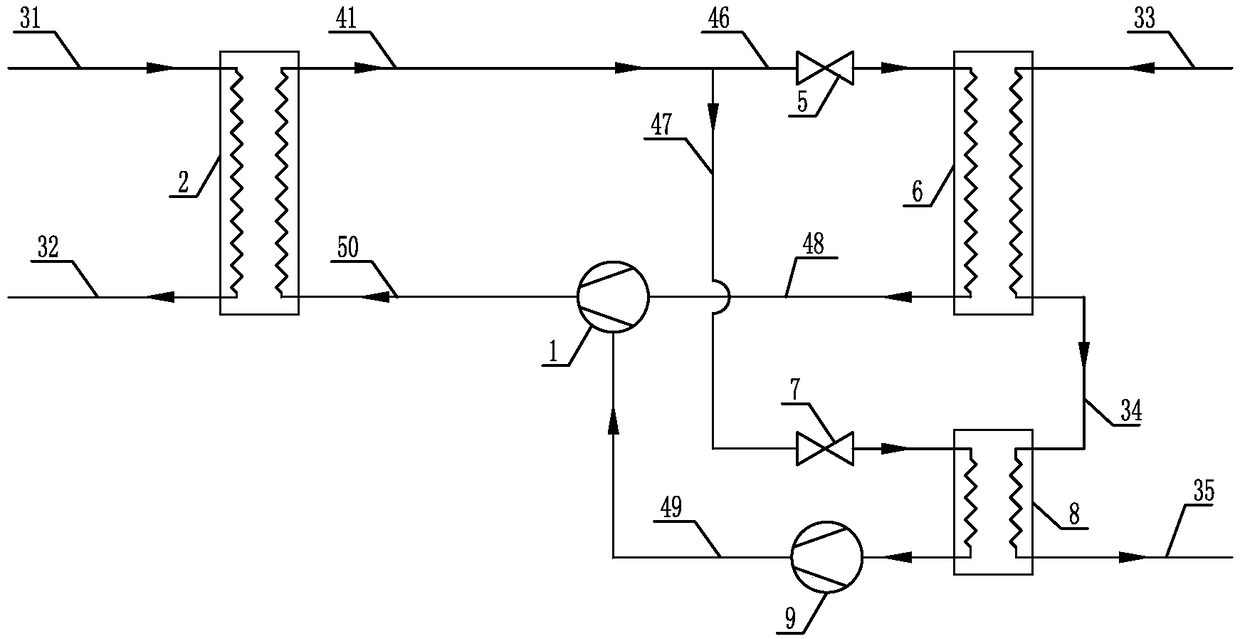
[0071] Specific implementation mode three: combination image 3 This embodiment is described. A two-stage compression heat pump cycle system for deep condensation of exhaust gas in this embodiment includes a first compressor 1, a heat pump condenser 2, a second throttling expansion valve 5, a heat pump first evaporator 6, The third throttling expansion valve 7, the second evaporator 8 of the heat pump, the second compressor 9, the first heat transfer medium pipeline 31, the second heat transfer medium pipeline 32, the first exhaust steam pipeline 33, the second exhaust steam pipeline Steam pipeline 34, third exhaust steam pipeline 35, first refrigerant pipeline 41, sixth refrigerant pipeline 46, seventh refrigerant pipeline 47, eighth refrigerant pipeline 48, ninth refrigerant pipeline Road 49 and the tenth refrigerant pipeline 50,

[0072] The outlet end of the first heat transfer medium pipeline 31 is connected to the heat medium inlet end of the heat pump condenser 2, and ...


PUM


Abstract

The invention discloses a double-stage compression heat pump circulation system for deeply condensing steam exhaust, and relates to a heat pump circulation system. The system aims to solve the problemthat existing conventional heat pumps are all low in heat pump evaporation temperature and performance coefficient when used for deep recycling of steam exhaust waste heat; the system comprises a first compressor, a heat pump condenser, a second throttling expansion valve, a heat pump first evaporator, a third throttling expansion valve, a heat pump second evaporator, a second compressor, a firstheat-carrying medium pipeline, a second heat-carrying medium pipeline, a first steam exhaust pipeline, a second steam exhaust pipeline, a third steam exhaust pipeline, a first refrigerant pipeline, asixth refrigerant pipeline, a seventh refrigerant pipeline, an eighth refrigerant pipeline, a ninth refrigerant pipeline and a tenth refrigerant pipeline. The system is used for deep heat recovery ofthe steam exhaust of a roller bed conveying line, and the performance coefficient of the heat pump is improved through cascade evaporation and cascade compression.

Description

technical field [0001] The invention relates to a heat pump circulation system, in particular to a two-stage compression heat pump circulation system for deep condensation of exhaust gas. Background technique [0002] In the industrial production that needs to use the evaporation and concentration process, most of the traditional multi-effect evaporation technology is used, which will generate a large amount of low-pressure secondary steam (exhaust steam). Without heat recovery, a lot of energy will be wasted. It is a very good energy-saving technology to adopt the vapor compression heat pump technology using Freon as the refrigerant to recover the exhaust steam heat. The coefficient of performance and efficiency of the heat pump are closely related to the evaporation temperature of the heat pump. The higher the evaporation temperature, the higher the coefficient of performance and efficiency of the heat pump. However, the waste heat of exhaust steam is composed of two par...

Claims


Application Information

Patent Timeline
Patent Type & Authority Applications(China)
IPC IPC(8): F25B30/02F25B41/06F25B41/325
CPCF25B30/02F25B41/31
Inventor 张承虎陈峰赵娟
Owner SHANGHAI ENN NEW ENERGY TECH CO LTD
Why Eureka
Try Eureka