
Two-stage-compression heat pump double-effect evaporation and condensation system

A concentration system, double-effect evaporation technology, applied in multi-effect evaporation, evaporation, evaporator accessories, etc., can solve the problem of high outlet temperature of two-effect juice vapor condensate water, high system energy consumption, and difficulty in vacuum degree of double-effect evaporation and concentration system maintain higher issues

Pending Publication Date: 2019-02-19
SHANGHAI ENN NEW ENERGY TECH CO LTD
View PDF8 Cites 5 Cited by
  • Summary
  • Abstract
  • Description
  • Claims
  • Application Information

AI Technical Summary

Problems solved by technology

[0005] The present invention solves the problem that the existing conventional double-effect evaporation concentration system does not recycle the waste heat of the second-effect juice vapor, resulting in high energy consumption of the system, and the outlet temperature of the second-effect juice vapor condensate water is generally high due to the generally high temperature of the natural cooling water. Higher, making it difficult to maintain the vacuum degree of the conventional double-effect evaporation and concentration system at a higher level, and then propose a two-stage compression heat pump double-effect evaporation and concentration system and device

Method used


Image

  • Two-stage-compression heat pump double-effect evaporation and condensation system
  • Two-stage-compression heat pump double-effect evaporation and condensation system
  • Two-stage-compression heat pump double-effect evaporation and condensation system

Examples


specific Embodiment approach 1

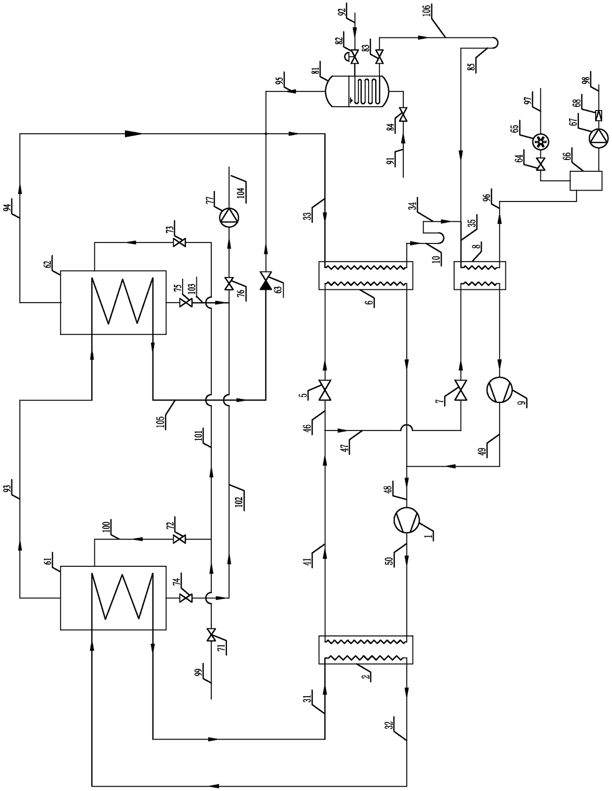
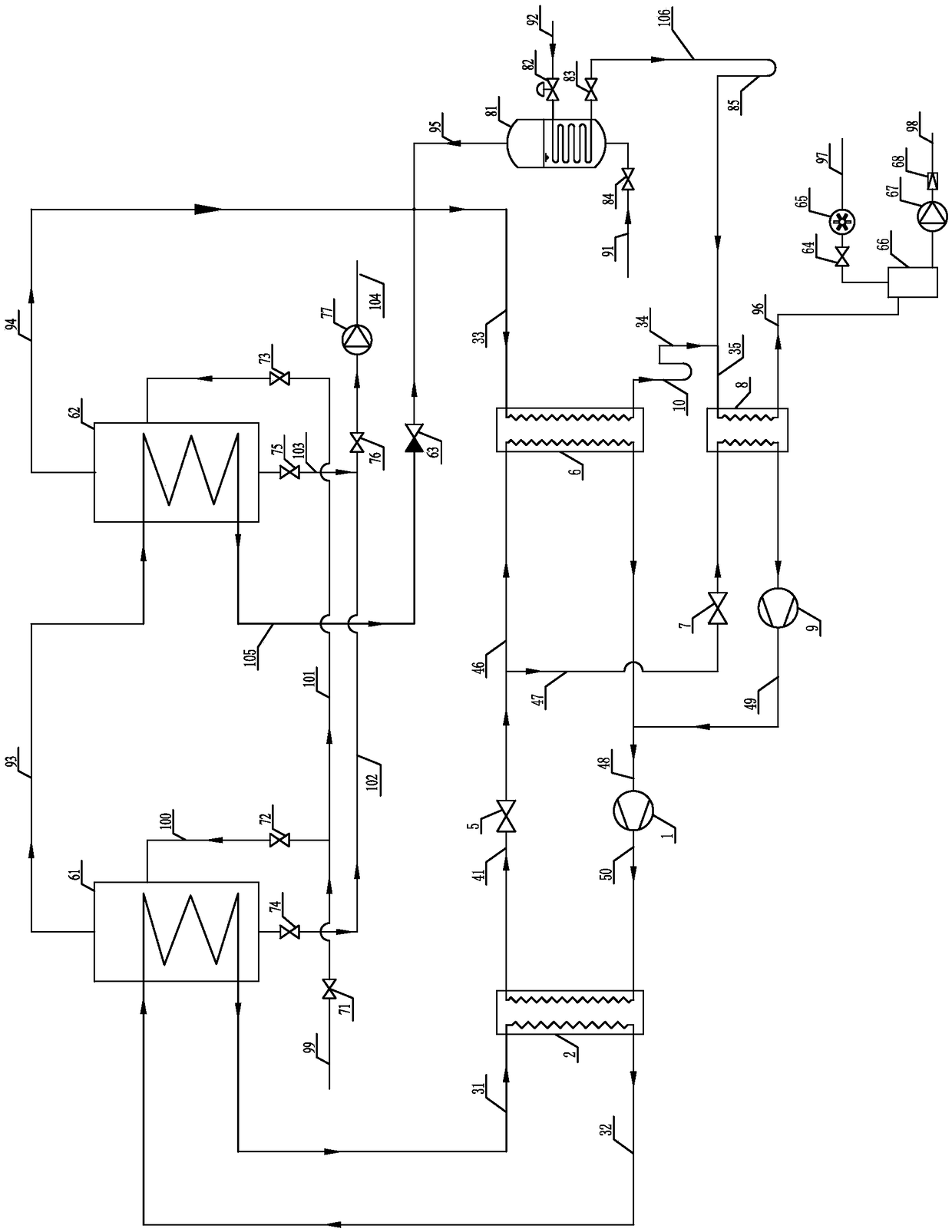
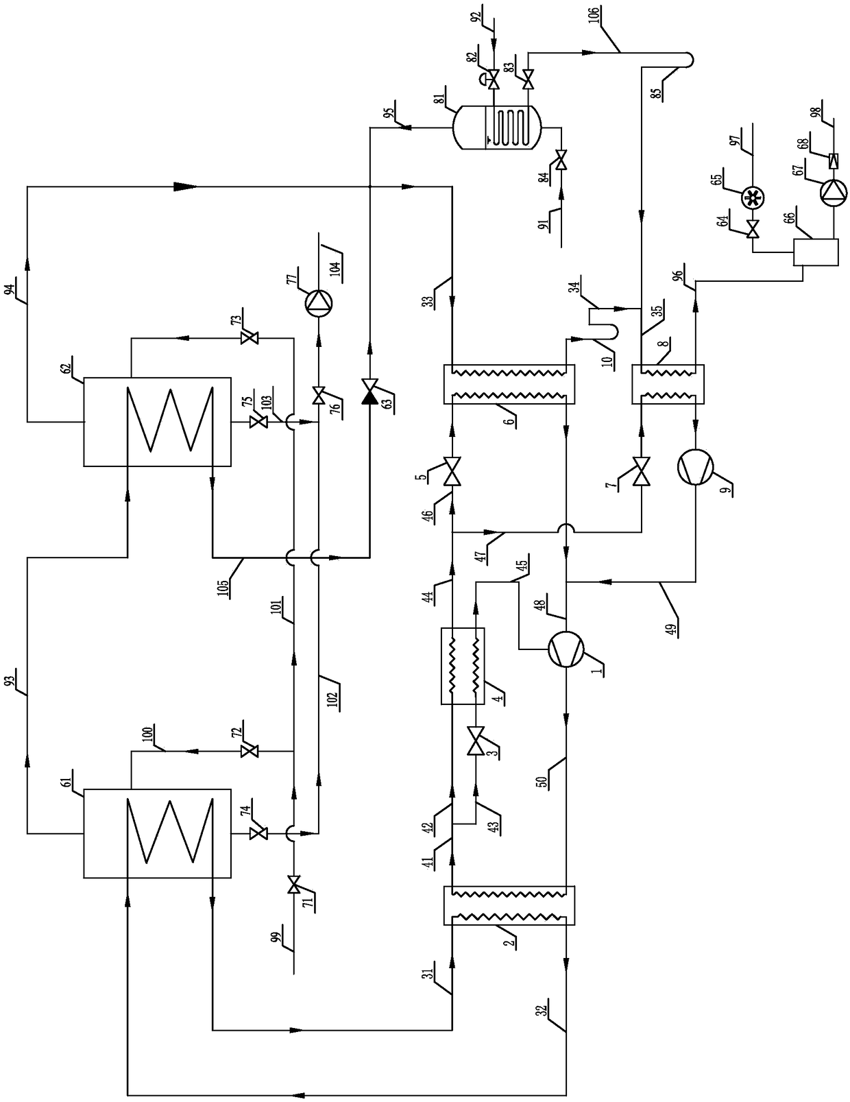
[0054] Specific implementation mode one: combine figure 1 Describe this embodiment, a two-stage compression heat pump double-effect evaporation and concentration system described in this embodiment includes a first compressor 1, a heat pump condenser 2, a second throttling expansion valve 5, a heat pump first evaporator 6, a second Three-throttle expansion valve 7, heat pump second evaporator 8, second compressor 9, first intermediary water circulation pipeline 31, second intermediary water circulation pipeline 32, first total exhaust steam pipeline 33, second total exhaust steam Pipeline 34, third total exhaust steam pipeline 35, first refrigerant pipeline 41, sixth refrigerant pipeline 46, seventh refrigerant pipeline 47, eighth refrigerant pipeline 48, ninth refrigerant pipeline Road 49, tenth refrigerant pipeline 50, first-effect evaporator 61, second-effect evaporator 62, vacuum control valve 64, vacuum pump 65, condensate collection tank 66, condensate discharge pump 67,...

specific Embodiment approach 2

[0077] Specific implementation mode two: combination figure 1 To illustrate this embodiment, an effective condensate water throttling device 63 is provided on the second first-effect juice vapor pipeline 105 in this embodiment. The undisclosed technical features in this embodiment are the same as those in the first embodiment.

[0078] In order to fully recover and utilize the waste heat of the condensed water of the first-effect juice vapor, the condensed water of the first-effect juice vapor and the second-effect juice vapor are merged into the first evaporator 6 of the heat pump for heat recovery. Since the pressure of the first-effect evaporator 61 is higher than that of the second-effect evaporator 62, a first-effect condensate throttling device 63 is installed on the second first-effect juice vapor pipeline 105 to control the first-effect evaporator 61 and the second-effect evaporator. The pressure difference between the effect evaporation tanks 62 (also controls the bo...

specific Embodiment approach 3

[0079] Specific implementation mode three: combination figure 1 To illustrate this embodiment, the second total exhaust steam pipeline 34 in this embodiment is provided with a first condensate water U-bend 10 , and the second start-up raw steam pipeline 106 is provided with a second condensate water U-shaped bend 85 . The undisclosed technical features in this embodiment are the same as those in the first or second specific embodiment.

[0080] The purpose of arranging the first condensate water U-shaped bend 10 and the second condensate water U-shaped bend 85 is to block the exhaust steam that is not completely condensed in the first evaporator 6 of the heat pump or the exhaust gas that is not completely condensed in the starter 81 The raw steam enters the second evaporator 8 of the heat pump to avoid a sharp increase in the refrigerant evaporation in the second evaporator 8 of the heat pump, thereby avoiding a sharp increase in the load of the second compressor 9 and causing...


PUM


Abstract

The invention relates to a double-effect evaporation, condensation and circulation system, in particular to a two-stage-compression heat pump double-effect evaporation and condensation system, and aims to solve the problem that existing conventional double-effect evaporation and condensation systems are high in energy consumption and low in vacuum degree. The double-effect evaporation and condensation system comprises a first compressor, a heat pump condenser, a heat pump first evaporator, a heat pump second evaporator, a second compressor, a first medium water circulation pipeline, a second medium water circulation pipeline, a primary-effect evaporation tank, a secondary-effect evaporation tank, a starter, a condensed water collection tank, a first start steam generating pipeline, a firstprimary-effect juice vapor pipeline, a secondary-effect juice vapor pipeline, a start secondary steam pipeline, a main condensed water pipeline, a second primary-effect juice vapor pipeline and a second start steam generating pipeline. The system can be applied in evaporation and condensation processes for industrial production of pharmacy, milk powder, amino acid and environment-friendly water treatment to recycle waste heat of secondary-effect juice vapor to achieve the objective of energy-saving production.

Description

technical field [0001] The invention relates to a system for double-effect evaporation and concentration using heat pump technology, in particular to a double-stage compression heat pump double-effect evaporation and concentration system. Background technique [0002] In the evaporation and concentration process of industrial production such as pharmaceuticals, milk powder, amino acids, and environmental protection water treatment, many factories use conventional double-effect evaporation and concentration systems. The conventional double-effect evaporation and concentration system provides raw steam from the boiler as the heat source for the first-effect evaporation, uses cooling water to pass through the water-steam condenser to condense the juice vapor of the second effect, and discharges the waste heat of the juice vapor of the second effect out of the system. Through the system energy conservation analysis and balance calculation, it is easy to find that the waste heat ...

Claims


Application Information

Patent Timeline
Patent Type & Authority Applications(China)
IPC IPC(8): B01D1/26B01D1/30
CPCB01D1/0011B01D1/0082B01D1/26B01D1/30
Inventor 张承虎陈峰陈长建赵娟
Owner SHANGHAI ENN NEW ENERGY TECH CO LTD
Learn More