16-point trimming system and 16-point trimming method for side wall of metal cylindrical resonator gyro

A technology of resonant gyroscope and metal cylinder, which is applied in the direction of gyroscope effect for speed measurement, gyroscope/steering induction equipment, instruments, etc., which can solve the problem of ignoring the static balance or symmetry of the resonant oscillator, the influence of the mode shape and natural frequency is large, and it is not easy to be high. Precision mechanical balance and other issues to achieve the effect of ensuring the consistency of deduplication, reducing frequency cracking, and improving gyroscope performance

Active Publication Date: 2019-03-08
TIANJIN NAVIGATION INSTR RES INST
View PDF6 Cites 8 Cited by
  • Summary
  • Abstract
  • Description
  • Claims
  • Application Information

AI Technical Summary

Problems solved by technology

The study found that the modification of the upper end face of the resonant ring has a great influence on the mode shape and natural frequency of the resonator, so that this balance method can produce a large frequency change with a small amount of modification, so the modification of the shape during the balance adjustment process The control accuracy of the amount is very high, especially in fine dynamic balance, the control of the modification amount is very difficult, and it is not easy to achieve high-precision mechanical balance, which virtually increases the manufacturing cost of the gyroscope and reduces the mass production efficiency.
In addition, the end-face trimming algorithm used in traditional practice ignores the static balance or symmetry of the harmonic oscillator after the trimming frequency is split, so that the static balance still needs to be performed after the trimming frequency is split, which virtually reduces the trimming efficiency

Method used


Image

  • 16-point trimming system and 16-point trimming method for side wall of metal cylindrical resonator gyro
  • 16-point trimming system and 16-point trimming method for side wall of metal cylindrical resonator gyro
  • 16-point trimming system and 16-point trimming method for side wall of metal cylindrical resonator gyro

Examples


Embodiment Construction

[0035] The embodiments of the present invention will be described in detail below in conjunction with the accompanying drawings. It should be noted that the embodiments are illustrative, not restrictive, and cannot limit the protection scope of the present invention.

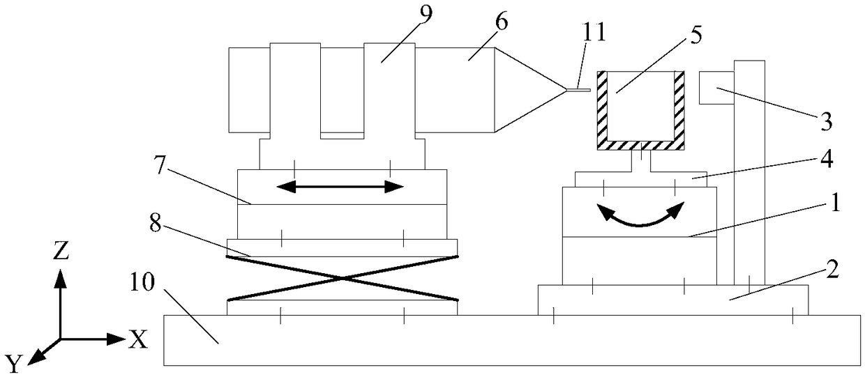
[0036] A 16-point adjustment system for the side wall of a metal cylindrical resonant gyroscope, including a bottom plate 10, a resonator positioning test device and a high-precision milling device. The resonator positioning test device is installed on the right side of the upper surface of the base plate. The resonator positioning test device The device includes a turntable 1, a support plate 2, an excitation and detection unit 3, and a conversion plate 4. The support plate is installed on the base plate, the turntable is installed on the left side of the upper surface of the support plate, and the excitation and detection unit is installed on the right side of the upper surface of the support plate. The plate 2...


PUM


Abstract

The invention relates to a 16-point trimming system and a 16-point trimming method for the side wall of a metal cylindrical resonator gyro. The device comprises a bottom plate, a harmonic oscillator positioning tester and a high-precision milling device. The method includes S1, mounting a harmonic oscillator, and defining the angular position of the harmonic oscillator; S2, determining the position of a high-frequency rigid shaft; S3, testing frequency cracking of the harmonic oscillator; S4, calculating the frequency cracking component corresponding to a trimming position, and calculating thedepth s and the length l of a required trimming groove; S5, performing sidewall grooving and trimming; S6, repeating the steps S2 to the step S5 until the frequency cracking of the harmonic oscillator meets the requirements. By the 16-point trimming system and the 16-point trimming method, the frequency cracking of the harmonic oscillator can be trimmed simply and quickly, and the symmetry of theharmonic oscillator after trimming is ensured.

Description

technical field [0001] The invention relates to the technical field of vibrating gyroscopes, in particular to a device and method for readjustment of 16 symmetrical positions on the side wall of a metal cylindrical resonant gyroscope. Background technique [0002] The metal cylindrical resonant gyroscope is a new type of solid wave gyroscope, which uses the inertial effect of elastic waves in the cylindrical structure to measure angular motion. It not only has the characteristics of high precision, low energy consumption, short preparation time, and wide operating temperature range unique to solid wave gyroscopes. , strong anti-ionizing radiation ability, good shock and vibration resistance, long service life, etc., and the processing of the cylindrical resonator is relatively simple, the excitation and sensitive electrodes are in the same plane, the difficulty of gyroscope manufacturing is significantly reduced, and the development and application prospects are extremely bro...

Claims


Application Information

Patent Timeline
IPC IPC(8): G01C19/5691G01C25/00
CPCG01C19/5691G01C25/00
Inventor 于得川刘仁龙魏艳勇齐国华王妍妍王得信
Owner TIANJIN NAVIGATION INSTR RES INST
Why Eureka
Try Eureka