
Distributed optical fiber temperature measurement system

A technology of distributed optical fiber and light detector, which is applied in thermometers, measuring devices, measuring heat, etc., can solve the problems of expensive data acquisition cards and high cost, and achieve the effect of reducing costs and saving user costs

Pending Publication Date: 2019-03-08
JIANGSU MINGJIANG MACHINERY MFG
View PDF0 Cites 0 Cited by
  • Summary
  • Abstract
  • Description
  • Claims
  • Application Information

AI Technical Summary

Problems solved by technology

Ordinary Raman DTS is positioned based on optical time domain reflectometer, and the positioning accuracy can only reach the order of meters, and further improving the positioning accuracy requires increasing the sampling rate of the data acquisition card, and the high-speed, high vertical resolution data acquisition card Very expensive, the cost of the whole system solution will be high

Method used


Image

  • Distributed optical fiber temperature measurement system

Examples


Embodiment Construction

[0018] The present invention will be further described below in conjunction with specific drawings and embodiments.

[0019] On the basis of the traditional DTS, the present invention adds a high-speed optical switch to the Stokes optical channel and the anti-Stokes optical channel respectively, and the controller controls the two output channels Ch1 and Ch2 of the dual-channel digital signal generator There is a variable time delay t between them; in order to achieve the purpose of using a data acquisition card with a low sampling rate to achieve high-precision positioning requirements.

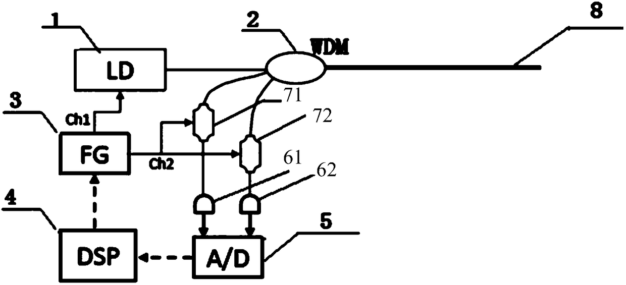
[0020] Such as figure 1 As shown, the distributed optical fiber temperature measurement system proposed by the present invention includes a high-speed response laser 1, a wavelength division multiplexer 2, a digital signal generator 3, a controller 4, a data acquisition card 5, a first photodetector 61, a Two optical detectors 62, a first high-speed optical switch 71, a second high-speed op...


PUM

PropertyMeasurementUnit
Pulse widthaaaaaaaaaa

Abstract

The invention provides a distributed optical fiber temperature measurement system. The distributed optical fiber temperature measurement system comprises a high speed response laser device, a wavelength division multiplexer, a digital signal generator, a controller, a data acquisition card, a first photodetector, a second photodetector, a first high speed photoswitch, a second high speed photoswitch and a sensing optical fiber; the controller is connected with the digital signal generator, one output channel Ch1 of the digital signal generator is connected with the high speed response laser device, and an output end of the high speed response laser device is connected with a first port of the wavelength division multiplexer; a second port of the wavelength division multiplexer is connectedwith the sensing optical fiber; a third port of the wavelength division multiplexer is connected with one end of the first high speed photoswitch, and the other end of the first high speed photoswitch is connected with one input end of the data acquisition card through the first photodetector; a fourth port of the wavelength division multiplexer is connected with one end of the second high speedphotoswitch, and the other end of the second high speed photoswitch is connected with the other input end of the data acquisition card through the second photodetector. The distributed optical fiber temperature measurement system is high in locating precision and low in cost.

Description

technical field [0001] The invention belongs to the field of distributed optical fiber temperature sensing, in particular to a distributed optical fiber temperature measurement system. Background technique [0002] Based on Raman's DTS (Distributed Optical Fiber Temperature Measurement System), the temperature information is obtained by comparing the intensity of Stokes light and anti-Stokes light. Ordinary Raman DTS is positioned based on optical time domain reflectometer, and the positioning accuracy can only reach the order of meters, and further improving the positioning accuracy requires increasing the sampling rate of the data acquisition card, and the high-speed, high vertical resolution data acquisition card Very expensive, the cost of the whole system solution will be high. Contents of the invention [0003] The purpose of the present invention is to overcome the deficiencies in the prior art and provide a distributed optical fiber temperature measurement system ...

Claims


Application Information

Patent Timeline
IPC IPC(8): G01K11/32G01K11/324
CPCG01K11/32G01K11/324
Inventor 周致中
Owner JIANGSU MINGJIANG MACHINERY MFG
Learn More