Airport runway lamplight detection system

An airport runway and detection system technology, applied in the aviation field, can solve the problems of increased maintenance costs and a large amount of manpower, and achieve the effect of simple operation and saving human resources

Inactive Publication Date: 2019-03-08
SONGFEI IND GRP CO LTD
View PDF0 Cites 1 Cited by
  • Summary
  • Abstract
  • Description
  • Claims
  • Application Information

AI Technical Summary

Problems solved by technology

[0002] With the improvement of the construction of airports and aprons, the construction of airports tends to be more mechanized and intelligent. While ensuring the safety and stability of equipment on the airport, it has become an effective model to optimize and improve the current manual management and maintenance work. , especially for the detection and maintenance of runway lights at airports, the number of runway lights used is relatively large, and they are evenly distributed on both sides of the long runway. If the runway lights are detected manually, a lot of manpower is required. , leading to an increase in maintenance costs. Considering that there is no product that automatically detects airport runway lights on the market, in order to optimize the detection and management of runway lights on the airport and reduce the cost of airport equipment management and maintenance, it is urgently needed Provide an intelligent, multi-functional and easy-to-operate airport runway light detection system

Method used


Image

  • Airport runway lamplight detection system
  • Airport runway lamplight detection system
  • Airport runway lamplight detection system

Examples


Embodiment Construction

[0028] The embodiments of the present invention will be described in detail below with reference to the accompanying drawings, but the present invention can be implemented in many different ways defined and covered by the claims.

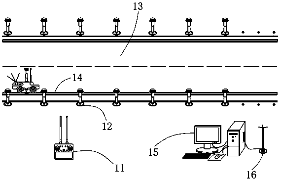
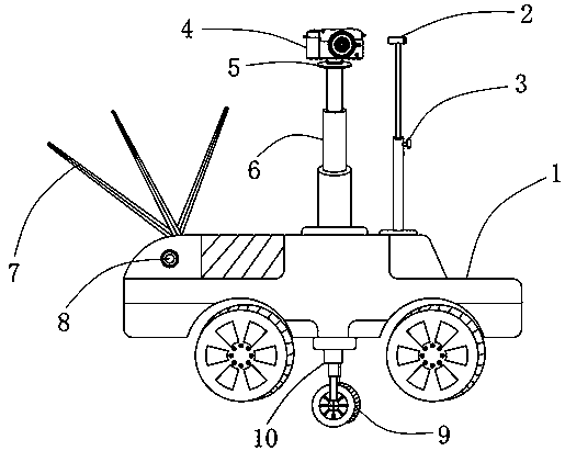
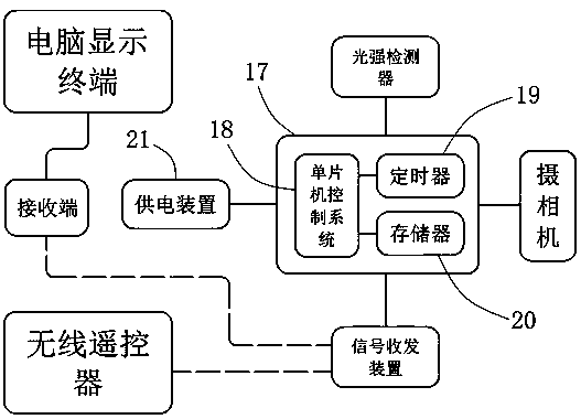
[0029] like Figure 1-3 As shown in , an airport runway light detection system provided by an embodiment of the present invention includes a detection car 1, a light intensity detector 2, an adjustment knob 3, a camera 4, a rotating disc 5, a telescopic arm 6, and a signal transceiver device 7. Charging hole 8, directional roller 9, elastic support arm 10, wireless remote control 11, runway lighting 12, directional slot 13, airport runway 14, computer display terminal 15, receiving end 16, PCB circuit board 17, single-chip microcomputer control system 18 , timer 19, memory 20 and power supply device 21.

[0030] Wherein, the light intensity detector 2, camera 4, signal transceiving device 7 and directional roller 9 are arranged on the detection tro...


PUM


Abstract

The invention relates to an airport runway lamplight detection system which comprises a detection trolley, a light intensity detector, a camera, a signal transceiving device, a directional roller, a wireless remote controller, runway lamplight, directional grooves, an airport runway, a computer display terminal, a receiving end, a PCB (printed circuit board), a single-chip microcomputer control system, a timer and a memorizer, wherein the light intensity detector, the camera, the signal transceiving device and the directional roller are arranged on the detection trolley; the single-chip microcomputer control system, the timer and the memorizer are arranged on the PCB, the PCB circuit board is arranged in the detection trolley, the directional grooves are formed in the edge positions of thetwo sides of the airport runway, the receiving end is in communication connection with the computer display terminal through a wire, and by use of the smart simple-to-operate airport runway lamplightdetection system comprising the single-chip microcomputer control system, the detection trolley, the wireless controller and the computer display terminal automatic detection of the runway lamplightis realized, and a lot of manpower resources are saved for an airport.

Description

technical field [0001] The invention relates to the field of aviation, in particular to an airport runway light detection system. Background technique [0002] With the improvement of the construction of airports and aprons, the construction of airports tends to be more mechanized and intelligent. While ensuring the safety and stability of equipment on the airport, it has become an effective model to optimize and improve the current manual management and maintenance work. , especially for the detection and maintenance of runway lights at airports, the number of runway lights used is relatively large, and they are evenly distributed on both sides of the long runway. If the runway lights are detected manually, a lot of manpower is required. , leading to an increase in maintenance costs. Considering that there is no product that automatically detects airport runway lights on the market, in order to optimize the detection and management of runway lights on the airport and reduce...

Claims


Application Information

Patent Timeline
IPC IPC(8): G01M11/02G01N21/95G08C17/02
CPCG01M11/0207G01N21/95G08C17/02
Inventor 宋照飞刘伟伦
Owner SONGFEI IND GRP CO LTD
Why Eureka
Try Eureka