Millimeter-wave radar antenna system and decoupling method

A millimeter-wave radar and antenna system technology, applied in radio wave measurement systems, radio wave reflection/re-radiation, utilization of re-radiation, etc., can solve the problems of ambiguous angle measurement results, few receiving channels, and high cost, and improve azimuth. The effect of angular measurement resolution, small radar footprint, and compact antenna arrangement

Pending Publication Date: 2019-03-08
ZHEJIANG LIBANG HEXIN INTELLIGENT BRAKING SYST CO LTD
View PDF0 Cites 19 Cited by
  • Summary
  • Abstract
  • Description
  • Claims
  • Application Information

AI Technical Summary

Problems solved by technology

[0004] 1. When the distance between the adjacent receiving antennas of the millimeter-wave radar is large, the angle measurement ambiguity exists in the main beamforming results. -α min ,α max ] is less than 90 degrees, when the target azimuth α is not within the radar angle measurement range, the target azimuth angle will be mapped to an angle α within the radar angle measurement range m , so that the radar receiving end cannot judge whether the real value of the angle is α or α m , that is, there is an ambiguity problem in the angle measurement results;
[0005] 2. In order to achieve higher resolution, multi-chip integration is adopted, the cost is very high, and the radar volume is relatively large;
[0006] 3. When the traditional three-transmitter and four-receive system has both pitch angle and azimuth angle measurement functions, there are often fewer virtual receiving channels, resulting in lower azimuth angle resolution

Method used


Image

  • Millimeter-wave radar antenna system and decoupling method
  • Millimeter-wave radar antenna system and decoupling method
  • Millimeter-wave radar antenna system and decoupling method

Examples


Embodiment Construction

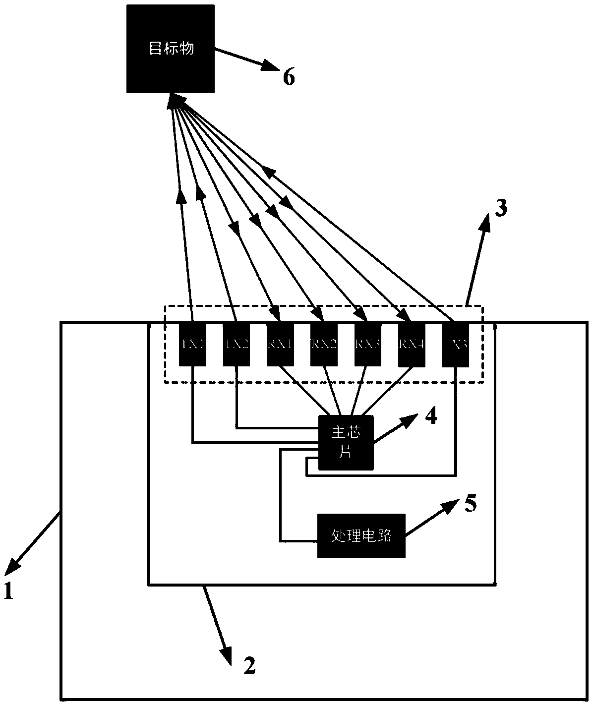
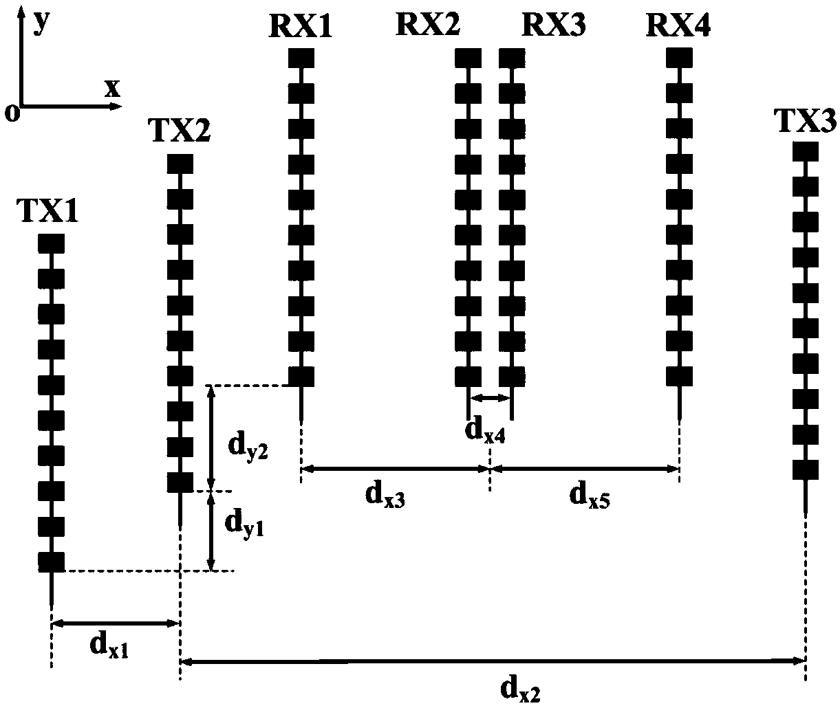
[0032] The millimeter-wave radar antenna system 2 described in this embodiment can be installed directly in front of or on the side of the vehicle 1, such as figure 1 As shown, the millimeter-wave radar antenna system 2 includes a multi-transmit and multiple-receive antenna array 3, a main processor 4 and a baseband processing circuit 5. This embodiment uses an antenna array that transmits three and receives four. The antenna array 3 includes a first transmitting antenna TX1, a second transmitting antenna TX2, a first receiving antenna RX1, a second receiving antenna RX2, a third receiving antenna RX3, a fourth receiving antenna RX4 and a third transmitting antenna TX3 arranged in sequence . Each transmitting antenna and receiving antenna is a microstrip antenna array, and the operating frequency is within the specified range (76-81GHz) of the automotive radar.

[0033] In this embodiment, the first transmitting antenna TX1, the second transmitting antenna TX2, and the third ...


PUM


Abstract

The invention discloses a millimeter-wave radar antenna system and a decoupling method. The antenna system comprises an antenna array, a main processor and a base band processing circuit, wherein theantenna array comprises at least two transmitting antennae and at least two receiving antennae, transmitting signals of the main processor are radiated to a target object through the transmitting antennae, the receiving antennae receive target reflected signals, the signals are mixed by the main processor to a base band, and the base band processing circuit analyzes and calculates target parameters. Compared with radar with the same performance, the antenna system adopts a single processing chip integration scheme, the cost is lower, and mainboard and antenna arrangement are more compact. By adopting the decoupling method, target azimuths and pitching angles can be calculated, the antenna system can produce more virtual receiving channels and improve the azimuth angle measurement resolution ratio according to the principle of a MIMO equivalent virtual array. By utilizing a mono-pulse antenna structure of the antenna system, the problem can be solved that main beamforming azimuth anglemeasurement is fuzzy when the separation distances of the receiving antennae are large.

Description

technical field [0001] The invention relates to an antenna system and a decoupling method, in particular to a millimeter wave radar antenna system and a decoupling method. Background technique [0002] Vehicle-mounted millimeter-wave radar, as an active preventive device to improve vehicle safety, has become the focus of major automobile manufacturers and consumers. Radar obtains the distance, speed, angle and other information of the object by processing the reflected signal of the target object. The main principle is that a specific waveform is first generated inside the radar, in which a small part of the beam signal is used as a reference signal, while the other large part of the beam signal is radiated by the antenna. The radiated signal is reflected when it encounters the target during the propagation process. The reflected signal is received by the receiving antenna and mixed with the reference signal. The baseband circuit on the radar board can process the mixed sig...

Claims


Application Information

Patent Timeline
Patent Type & Authority Applications(China)
IPC IPC(8): G01S13/93G01S7/03
CPCG01S13/931G01S7/03
Inventor 陈启生其他发明人请求不公开姓名
Owner ZHEJIANG LIBANG HEXIN INTELLIGENT BRAKING SYST CO LTD
Why Eureka
Try Eureka