An improved safety injection box

A safety injection box and improved technology, applied in the direction of reducing greenhouse gases, climate sustainability, reactors, etc., can solve the problems of injection flow fluctuation, inconvenient maintenance, complex structure, etc., to simplify the structure, facilitate manufacturing and The effect of maintenance and reliability improvement

Active Publication Date: 2020-04-21
NUCLEAR POWER INSTITUTE OF CHINA
View PDF8 Cites 0 Cited by
  • Summary
  • Abstract
  • Description
  • Claims
  • Application Information

AI Technical Summary

Problems solved by technology

[0005] The purpose of the present invention is to provide an improved safety injection tank to solve the complex structure in the prior art, inconvenient maintenance, and unstable coolant output when switching from the refilling stage to the resubmerging stage, causing the safety injection box to be in the state. Problems with fluctuating injection flow during early reflooding that reduce core reflooding efficiency

Method used


Image

  • An improved safety injection box
  • An improved safety injection box
  • An improved safety injection box

Examples


Embodiment 1

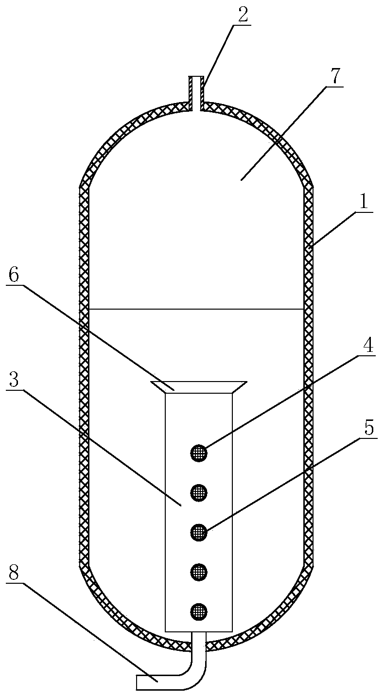
[0041] Such as figure 1 An improved safety injection box shown includes a housing 1, the top of the housing 1 is provided with an air inlet pipe 2, and the housing 1 is provided with a standpipe 3, the top of the standpipe 3 is an open end, and the bottom end of the standpipe 3 It is a closed end, and a drain pipe 8 is arranged on the closed end of the standpipe 3, and the drain pipe 8 communicates with the inside of the standpipe 3 and the outside of the housing 1, and a plurality of Through hole 4; the top of the standpipe 3 is provided with an anti-vortex device 6, and the diameter of the anti-vortex device 6 gradually decreases from top to bottom; the anti-vortex device 6 and the through hole 4 are all provided with a filter screen 5 ; The distance between two adjacent through holes 4 gradually decreases from top to bottom.

[0042] In some embodiments, the number of through holes 4 is six.

[0043] When in use, the liquid discharge pipe 8 is opened, and nitrogen gas is ...

Embodiment 2

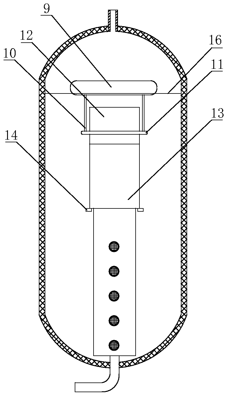
[0045] Such as figure 2 As shown, on the basis of Embodiment 1, it also includes a main floating plate 9 above the standpipe 3, the lower surface of the main floating plate 9 is connected with an extension tube through a connecting mechanism, and the extension tube is sleeved on the standpipe 3 Externally, the top of the extension tube is an open end, and there is a gap between the top of the extension tube and the lower surface of the main floating plate 9; the length of the standpipe 3 is 1.2 to 2 times the length of the extension tube; The gap height of the lower surface of the floating plate 9 is 10-25 cm.

[0046] Such as figure 2 As shown, when the coolant level 16 is higher than the open end of the riser 3, the gap height between the extension tube and the main floating plate 9 is fixed, the distance between the initial coolant level 16 and the standard line, and the coolant The drop of the liquid level 16 will not change the distance between the coolant liquid leve...

Embodiment 3

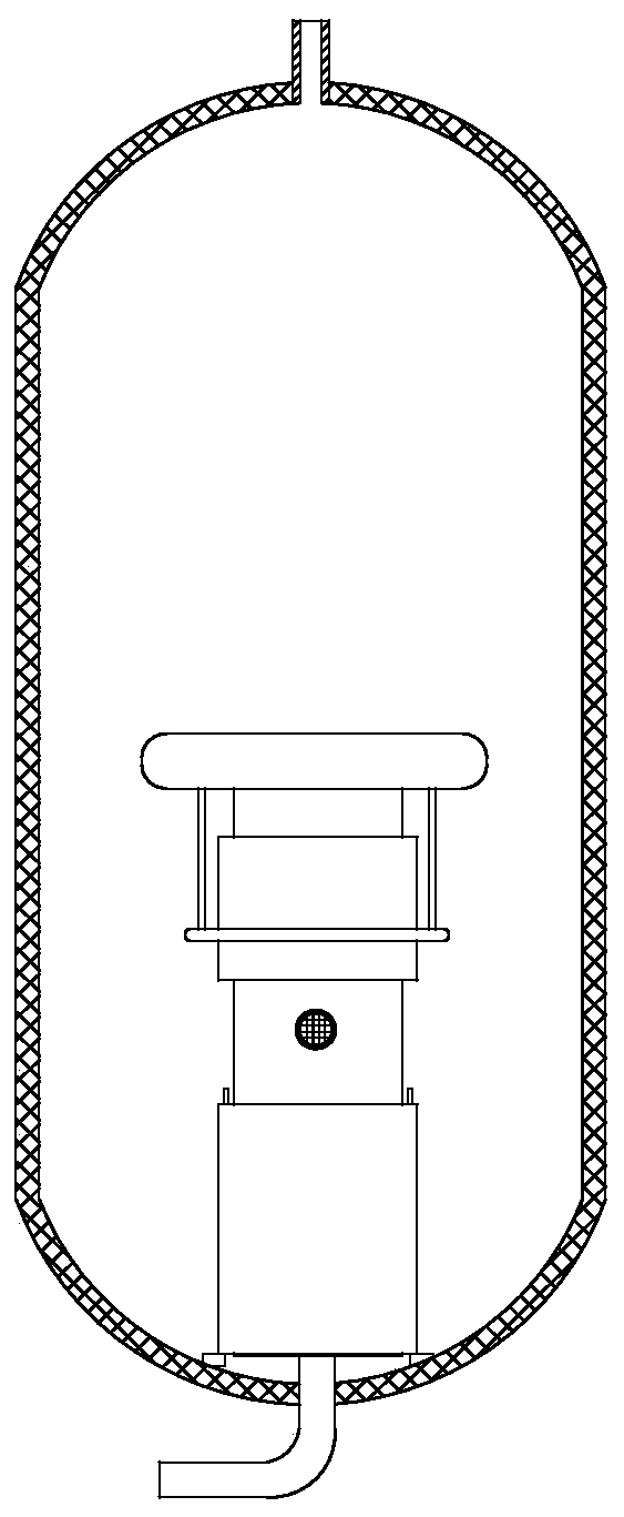
[0049] Such as Figure 2 ~ Figure 4 As shown, on the basis of Embodiment 2, the extension tube includes a first extension tube 12 and a second extension tube 13, wherein the first extension tube 12 is located above the second extension tube 13, and the connecting mechanism is connected with the first extension tube The bottom end of the second extension tube 13 is provided with an auxiliary floating plate 14; the connecting mechanism includes a connecting rod 10 and a connecting ring 11, the connecting rod 10 is fixed on the lower surface of the main floating plate 9, and the connecting rod 10 The bottom end is fixed with a connecting ring 11, and the connecting ring 11 is fixedly sleeved on the outside of the first extension tube 12; the top of the second extension tube 13 is provided with a card protrusion 15, and the bottom end of the first extension tube 12 is provided with a A card slot matching the card protrusion 15.

[0050] Such as figure 2 As shown, when the coola...


PUM


Abstract

The invention discloses an improved safety injection box, which comprises a casing, an air intake pipe is arranged on the top of the casing, a standpipe is arranged inside the casing, the top of the standpipe is an open end, and the bottom of the standpipe The end is a closed end, and the closed end of the standpipe is provided with a drain pipe, which connects the inside of the standpipe and the outside of the housing, and a plurality of through holes are opened on the side wall of the standpipe from top to bottom. The standpipe of the present invention can function as a damper, and the through hole provided on the standpipe can function as a small pipe, so the present invention does not need to set a damper and a small pipe, and self-adaptive adjustment of flow can be realized only with the standpipe The function of the safety injection box greatly simplifies the structure of the safety injection box, which is convenient for device manufacture and maintenance; the multiple through holes arranged on the standpipe from top to bottom make the coolant output from the safety injection box The flow rate decreases gradually and steadily, which significantly improves the reliability of the safety injection box operation.

Description

technical field [0001] The invention relates to the field of safety injection systems of nuclear power plants, in particular to an improved safety injection box. Background technique [0002] After a large break loss of water accident in a pressurized water reactor nuclear power plant, the safety injection system is required to provide different flow requirements for the refilling stage, reflooding stage and long-term cooling stage after the spraying is completed. The traditional PWR relies on the safety injection tank to meet the large flow demand in the refilling stage and the small flow demand in the early stage of reflooding, and then relies on the low-pressure safety injection pump to meet the small flow demand in the late reflooding and long-term cooling stages. [0003] Therefore, the booster tank needs to provide a larger coolant flow during the refilling phase and a smaller coolant flow during the reflooding phase. Gou Junli and others provided a safety injection b...

Claims


Application Information

Patent Timeline
Patent Type & Authority Patents(China)
IPC IPC(8): G21C15/18
CPCG21C15/18Y02E30/30
Inventor 党高健蒋孝蔚黄代顺冉旭丁书华高颖贤李喆何晓强袁红胜钟明君张渝卢川
Owner NUCLEAR POWER INSTITUTE OF CHINA
Why Eureka
Try Eureka