A static contact structure and its fixed forming process with arc striking angle

A technology of molding process and arc striking angle, which is applied in the direction of breaker switch contacts, electrical components, electric switches, etc., can solve the problems of injury to the operator's body, loss of arc striking angle coating, and cost increase, so as to improve factory efficiency and avoid The matching process and the effect of reducing the cost of electroplating

Active Publication Date: 2020-04-14
瑞睿电气(浙江)有限公司
View PDF3 Cites 0 Cited by
  • Summary
  • Abstract
  • Description
  • Claims
  • Application Information

AI Technical Summary

Problems solved by technology

[0005] The resulting problems are: 1. When the arc ignition angle is welded with the connecting plate, the arc ignition angle coating is lost, and the arc ignition effect is reduced
[0006] Because one of iron and copper has high resistance and the other has low resistance, there is a large difference in resistance. When welding the arc starting angle and the connecting plate, it is easy to cause arc slag sputtering and hurt the operator's body.
At the same time, the weldability of the welding part is not good, and there is a situation of virtual welding, which causes the arc angle to fall off during use.
[0007] When the arc ignition angle is pickled before the silver plating process, the copper layer becomes thinner after pickling, resulting in the failure of the silver layer to be plated, the thinner silver layer, and the surface layering, etc., resulting in the failure of the salt spray test and the poor arc ignition effect. good
[0008] Copper-plated and then silver-plated at the starting arc leads to increased cost

Method used


Image

  • A static contact structure and its fixed forming process with arc striking angle
  • A static contact structure and its fixed forming process with arc striking angle

Examples


Embodiment Construction

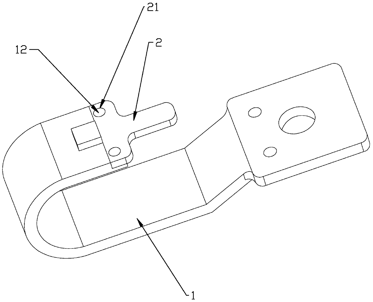
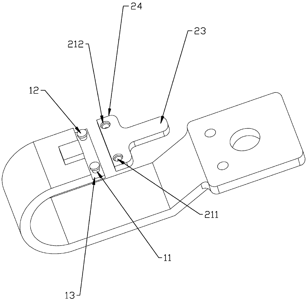
[0029] Such as Figure 1-2 As shown, a fixed forming process of the static contact and the arc striking angle 2 includes the following steps,

[0030] S1. Stamping and forming the connecting plate 1, and forming a stretching boss 11 at the connecting part of the connecting plate 1 and the arc striking angle 2;

[0031] S2, stamping the arc starting angle 2, and forming the installation through hole 21 adapted to the stretching boss 11 at the connection part between the arc starting angle 2 and the connecting plate 1, and the depth of the installation through hole 21 is smaller than that of the stretching boss height of table 11;

[0032] S3. Galvanizing the arc striking angle 2;

[0033] S4. Insert the stretching boss 11 into the installation through hole 21 and extend it to the outside of the installation through hole 21, then punch the exposed part of the stretching boss 11, and drive the stretching boss 11 to deform to form a limit flange 12, so that the arc striking angl...


PUM


Abstract

The invention relates to a static contact structure and a fixed formation process for the same and an arc striking angle. By directly growing a stretching boss during the formation process of a connection plate, the step of arranging a fastening piece such as a bolt and a rivet during the fixed connection process is directly omitted, annealing of a welding process on the arc striking angle and a copper piece is prevented, the fixed installation speed of the arc striking angle and the connection plate is greatly improved by reducing the time of the step of fastening piece alignment and installation, an installation part and the installation step are reduced particularly when automatic equipment is used for fixing the arc striking angle, the structure of the automatic equipment can be correspondingly simplified, and the cost of researching and manufacturing the automatic equipment is reduced. Moreover, the part selection process is prevented, and the factory benefit is improved; and meanwhile, the arc striking angle is changed to be riveted after zinc plating, a traditional process of copper plating first and then silver plating is not depended, the electroplating cost is greatly reduced, and arc slag sputtering caused by relatively large resistance difference between an iron material (the arc striking angle) and a copper material (a contact) during welding operation is reduced.

Description

technical field [0001] The invention relates to the technical field of electrical switches, in particular to a structure of a static contact on a molded case circuit breaker and a process for fixing it to an arc striking angle. Background technique [0002] An important performance index of the circuit breaker is the arc extinguishing ability. At present, the circuit breaker usually uses the arc starting angle to introduce the arc into the arc extinguishing chamber for arc extinguishing treatment. In the prior art, the arc starting angle is usually welded with the connecting plate by welding. The connecting plate is welded with the wiring plate again. [0003] The role of arc strike angle is very important. In a nutshell, the function of the arc strike angle is to quickly introduce the arc generated by the moving and static contacts into the arc extinguishing chamber when breaking the short-circuit current, and produce a current limiting effect in the process to protect the...

Claims


Application Information

Patent Timeline
Patent Type & Authority Patents(China)
IPC IPC(8): H01H11/00H01H73/04H01H73/18
CPCH01H11/00H01H73/04H01H73/18
Inventor 吴起军沈高强杨宇郑立坤
Owner 瑞睿电气(浙江)有限公司
Why Eureka
Try Eureka