LTCC substrate with built-in microchannels and high heat dissipation performance as well as manufacturing method thereof

A manufacturing method and micro-channel technology, applied in semiconductor/solid-state device manufacturing, electrical components, electrical solid-state devices, etc., can solve problems such as extremely high heat dissipation requirements, low heat dissipation power, and inability to meet development needs, and achieve high heat dissipation, The effect of improving the heat dissipation performance

Active Publication Date: 2019-03-08
XIAN MICROELECTRONICS TECH INST
View PDF5 Cites 13 Cited by
  • Summary
  • Abstract
  • Description
  • Claims
  • Application Information

AI Technical Summary

Problems solved by technology

[0002] Modern electronic equipment is constantly facing the development requirements of high-density integration and high power. Although LTCC substrates have the characteristics of high-density integration, their heat dissipation power is low, which cannot meet the development needs. Micro-channels are embedded in LTCC substrates to utilize heat conduction. The fluid improves the heat conduction efficiency of the substrate, which is the key technology to realize the high density and high heat con

Method used


Image

  • LTCC substrate with built-in microchannels and high heat dissipation performance as well as manufacturing method thereof
  • LTCC substrate with built-in microchannels and high heat dissipation performance as well as manufacturing method thereof
  • LTCC substrate with built-in microchannels and high heat dissipation performance as well as manufacturing method thereof

Examples


Embodiment Construction

[0032] The present invention will be further described in detail below in conjunction with specific embodiments, which are explanations of the present invention rather than limitations.

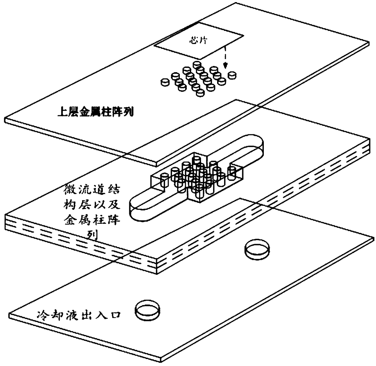
[0033] The structure schematic diagram of the LTCC substrate with built-in micro-channel according to the present invention is as follows figure 1 As shown, it includes the upper part, the middle part and the lower part; the upper part is provided with an array of metal pillars, and the middle part is provided with a cavity formed by two microchannels connected with a hollow cavity, and the hollow cavity is provided with an array of metal pillars. The metal pillars of the upper part correspond to the metal pillars of the middle part one by one; the lower part is provided with a cooling liquid inlet hole and a cooling liquid outlet hole, and the cooling liquid inlet hole and the cooling liquid outlet hole respectively correspond to the two microchannels of the middle part.

[0034] Its structu...


PUM


Abstract

The invention provides an LTCC substrate with built-in microchannels and high heat dissipation performance as well as a manufacturing method thereof. The LTCC substrate comprises an upper layer part,a middle layer part and a lower layer part; the upper layer part is provided with a metal column array, the middle layer part is provided with a cavity formed by two microchannels and a hollow cavitywhich are communicated, the hollow cavity is internally provided with a metal column array, and metal columns of the upper layer part and metal columns of the middle layer part are in one-to-one correspondence; and the lower layer part is provided with a cooling liquid outlet/inlet hole. The manufacturing method comprises the following steps: preparing a carbon belt green body sample with a metalcolumn array and a pure carbon belt green body sample; preparing an upper layer green ceramic disc, a middle layer green ceramic disc and a lower layer green ceramic disc respectively corresponding tothe upper layer part, the middle layer part and the lower layer part; and laminating the carbon belt green body sample and the green ceramic discs in a corresponding manner, and sintering. The substrate provided by the invention is provided with the metal column arrays, the cavity and the microchannels, and the metal column array in an upper layer transfers heat produced by a chip to the metal column array in a middle layer; and the metal column array in the middle layer transfers heat to a heat dissipation medium inside the cavity by virtue of increased surface area, so that the heat dissipation performance of the substrate is improved.

Description

technical field [0001] The invention belongs to the technical field of semiconductor hybrid integrated circuits, and relates to a high heat dissipation LTCC substrate with a built-in microflow channel and a manufacturing method thereof. Background technique [0002] Modern electronic equipment is constantly facing the development requirements of high-density integration and high power. Although LTCC substrates have the characteristics of high-density integration, their heat dissipation power is low, which cannot meet the development needs. The fluid improves the heat conduction efficiency of the substrate, which is the key technology to realize the high density and high heat conduction LTCC substrate. [0003] Usually, as a high-density integrated ceramic substrate, the LTCC substrate has a thermal conductivity of 2-3W / m-k, which is difficult to meet the heat dissipation requirements of high-power circuits, especially for highly integrated SiP products and LTCC RF / microwave ...

Claims


Application Information

Patent Timeline
IPC IPC(8): H01L21/48H01L23/498
CPCH01L21/4857H01L21/4871H01L23/49822H01L23/49838
Inventor 肖刚陈宁王明琼
Owner XIAN MICROELECTRONICS TECH INST
Why Eureka
Try Eureka