A Low Profile Broadband Filter Antenna
A filter antenna and low-profile technology, which is applied in the field of filter antennas, can solve the problems of narrow operating frequency band, high profile, and large size of directional filter microstrip antennas, and achieve the effects of miniaturization, profile reduction, and surface area reduction
- Summary
- Abstract
- Description
- Claims
- Application Information
AI Technical Summary
Problems solved by technology
Method used
Image
Examples
Embodiment 1
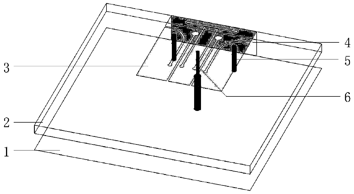
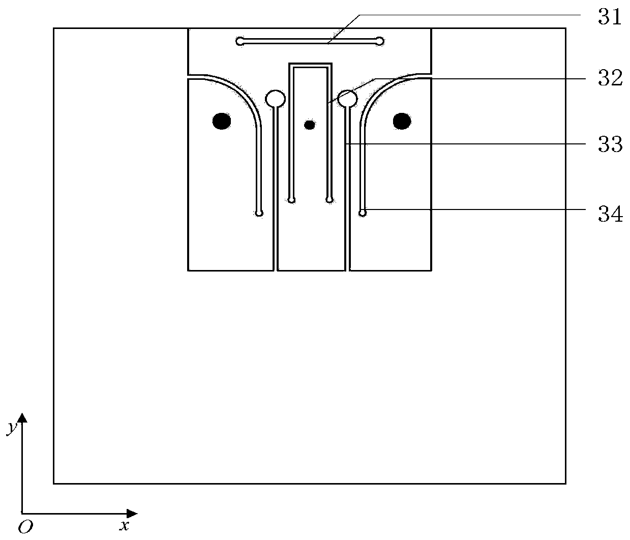
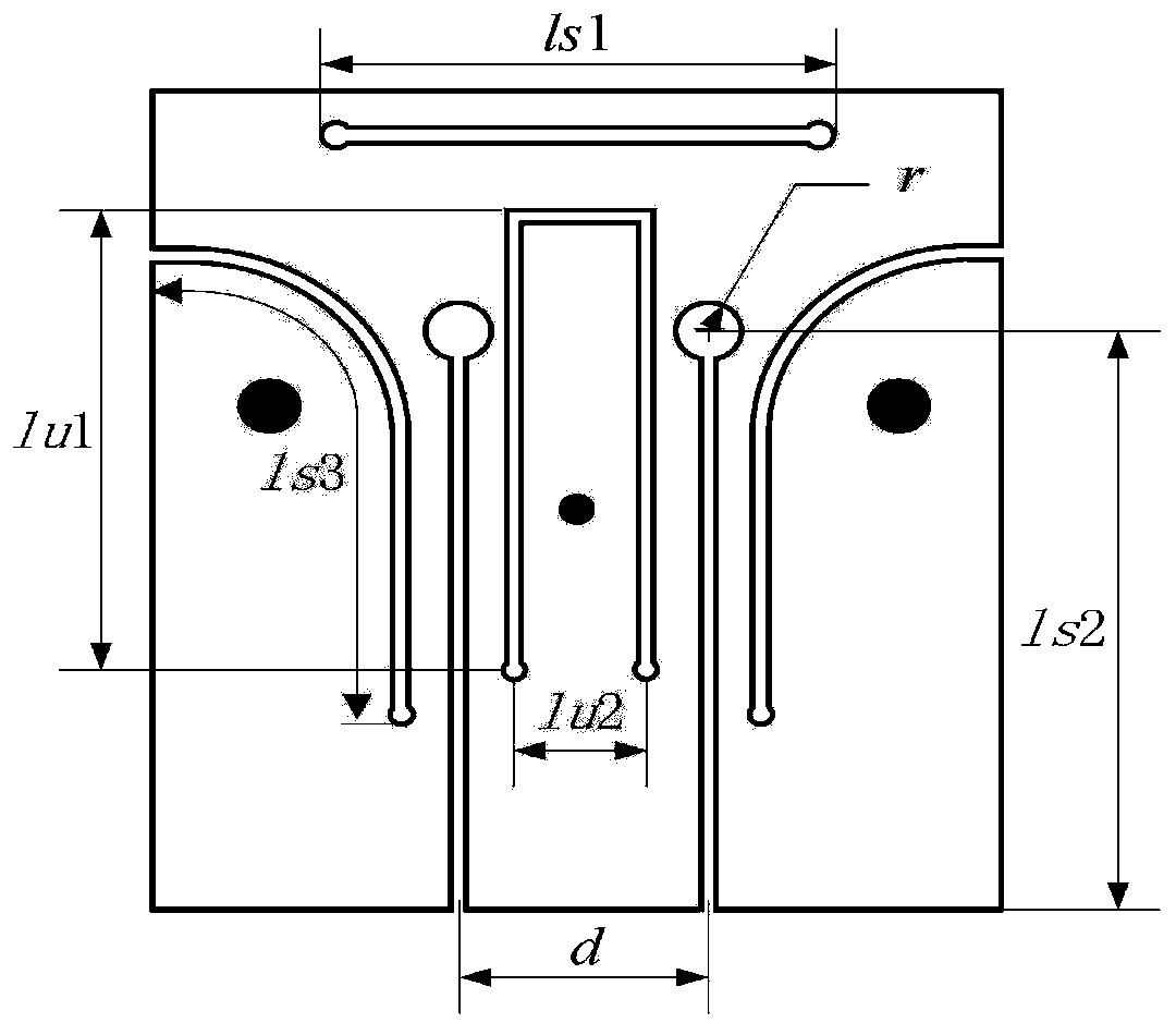
[0026] refer to figure 1 , refer to figure 2 and image 3
[0027] A low-profile broadband filter antenna, including a metal floor 1, a dielectric plate 2 arranged directly above the metal floor 1, a rectangular metal patch 3 located at the edge of the upper surface of the dielectric plate 2, a rectangular metal wall 4 on the side, and a Two metal short-circuit posts 5 and coaxial probes 6 of the board 2; one end of the rectangular metal wall 4 is connected to the edge of the rectangular metal patch 3, and the other end extends to the edge of the metal floor 1, and it is characterized in that the The first slit 31 with both ends of the closed structure is etched on one side of the edge of the rectangular metal patch 3 connected to the rectangular metal wall 4, and the central part of the rectangular metal patch 3 is etched with an opening facing the other side. U-shaped slit 32, the two sides of the U-shaped slit 32 are respectively etched with the same second slit 33, one...
Embodiment 2
[0035] The structure of embodiment 2 is the same as that of embodiment 1, only the following parameters have been adjusted:
[0036] The two arms of the U-shaped slit 32 are parallel to each other, the length of the two arms of the U-shaped slit 32 is lu1, and the distance between them is lu2, wherein lu1=13.5mm, lu2=2mm.
[0037] The second slits are parallel to each other, the length of the second slits is ls2, and the distance is d, wherein, ls2=16mm, d=4mm.
[0038] The straight segments of the third slit 34 are parallel to each other, and the total length of the third slit 34 is ls3, wherein ls3=14.5mm.
[0039] The length of the first slit 31 is ls1, wherein ls1=10mm.
Embodiment 3
[0041] The structure of embodiment 3 is the same as that of embodiment 1, only the following parameters have been adjusted:
[0042] The two arms of the U-shaped slit 32 are parallel to each other, the length of the two arms of the U-shaped slit 32 is lu1, and the distance between them is lu2, wherein lu1=19.5mm, lu2=6mm.
[0043] The second slits are parallel to each other, the length of the second slits is ls2, and the distance is d, wherein, ls2=24mm, d=8mm.
[0044] The straight segments of the third slit 34 are parallel to each other, and the total length of the third slit 34 is ls3, wherein ls3=21.5mm.
[0045] The length of the first slit 31 is ls1, wherein ls1=14mm.
[0046] Below in conjunction with simulation experiment, technical effect of the present invention is described further:
[0047] 1. Simulation conditions and content:
[0048] The low-profile broadband filter antenna described in Embodiment 1 is placed on the xoy plane, and the above-mentioned Embodime...
PUM
 Abstract
Description
Claims
Application Information
 - R&D
- Intellectual Property
- Life Sciences
- Materials
- Tech Scout
- Unparalleled Data Quality
- Higher Quality Content
- 60% Fewer Hallucinations
Browse by: Latest US Patents, China's latest patents, Technical Efficacy Thesaurus, Application Domain, Technology Topic, Popular Technical Reports.
© 2025 PatSnap. All rights reserved.Legal|Privacy policy|Modern Slavery Act Transparency Statement|Sitemap|About US| Contact US: help@patsnap.com


