Installation support for solar photovoltaic battery component
A technology for photovoltaic cells and mounting brackets, applied in photovoltaic power generation, supporting structures of photovoltaic modules, photovoltaic modules, etc., can solve problems such as limiting the range of use of mounting brackets, inconvenient installation, and low installation efficiency, so as to improve energy conversion effects, Improve the applicability and facilitate the effect of moving down
- Summary
- Abstract
- Description
- Claims
- Application Information
AI Technical Summary
Problems solved by technology
Method used
Image
Examples
Embodiment 1
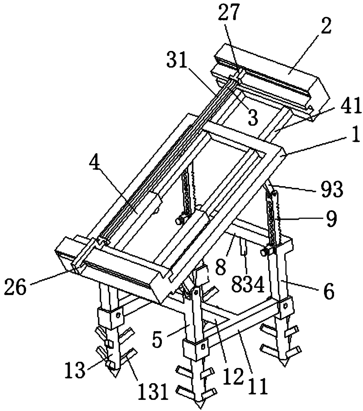
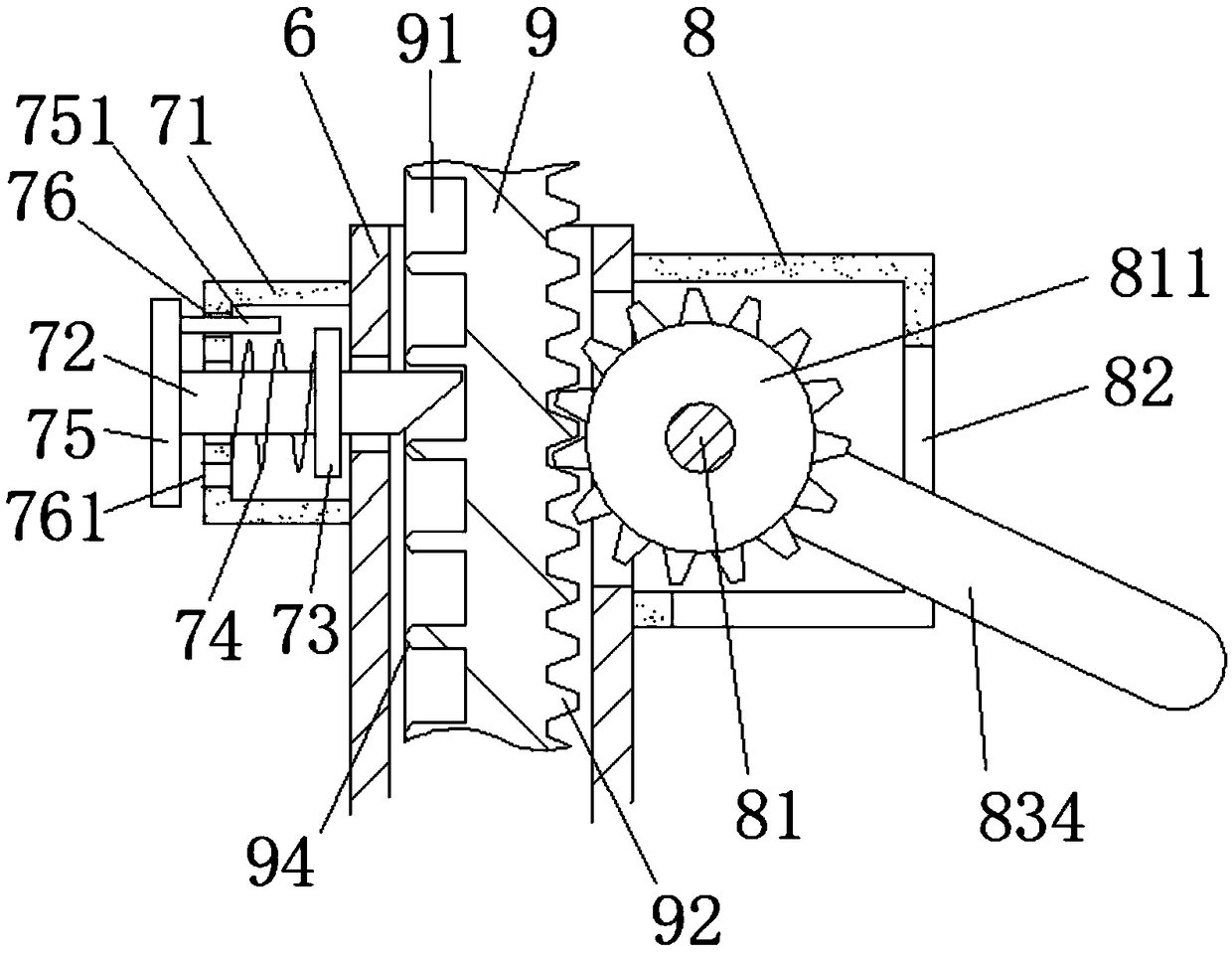
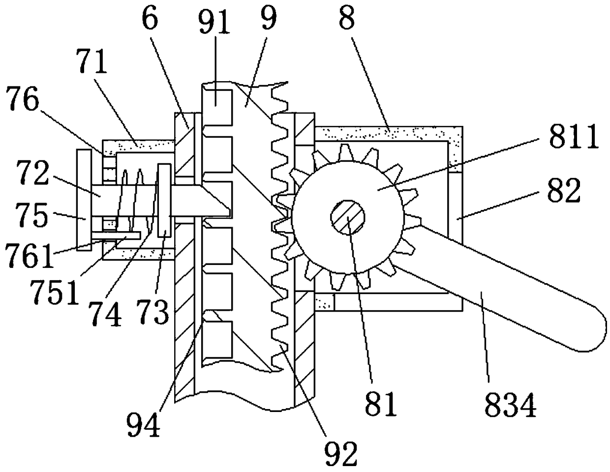
[0035] Embodiment 1: A kind of mounting bracket for solar photovoltaic cell assembly, refer to the attached Figure 1-9 , including a placement frame 1, a solar photovoltaic panel installed on the placement frame 1, two first support rods 5 supported on one side of the placement frame 1, and two second support tubes 6 on the opposite side, the first The top of the support rod 5 is hinged on the placement frame 1, one end of a telescopic rod 9 is inserted into the second support tube 6, and the other end of the telescopic rod 9 is flexibly connected with the placement frame 1 through an adjustment rod 93, and the two ends of the adjustment rod 93 are The ends are respectively hinged on the telescopic rod 9 and the placement frame 1; on the side wall of the telescopic rod 9, there are at least two adjustment holes 91 spaced along the length direction of the telescopic rod 9, which are located at the front end of the insertion rod 72 in the positioning housing 71. Embedded in the...
Embodiment 2
[0042] Embodiment 2: A kind of mounting bracket for solar photovoltaic cell assembly, refer to the attached Figure 2-10 , including a placement frame 1, a solar photovoltaic panel installed on the placement frame 1, two first support rods 5 supported on one side of the placement frame 1, and two second support tubes 6 on the opposite side, the first The top of the support rod 5 is hinged on the placement frame 1, one end of a telescopic rod 9 is inserted into the second support tube 6, and the other end of the telescopic rod 9 is flexibly connected with the placement frame 1 through an adjustment rod 93, and the two ends of the adjustment rod 93 are The ends are respectively hinged on the telescopic rod 9 and the placement frame 1; on the side wall of the telescopic rod 9, there are at least two adjustment holes 91 spaced along the length direction of the telescopic rod 9, which are located at the front end of the insertion rod 72 in the positioning housing 71. Embedded in th...
PUM
 Abstract
Description
Claims
Application Information
 - R&D
- Intellectual Property
- Life Sciences
- Materials
- Tech Scout
- Unparalleled Data Quality
- Higher Quality Content
- 60% Fewer Hallucinations
Browse by: Latest US Patents, China's latest patents, Technical Efficacy Thesaurus, Application Domain, Technology Topic, Popular Technical Reports.
© 2025 PatSnap. All rights reserved.Legal|Privacy policy|Modern Slavery Act Transparency Statement|Sitemap|About US| Contact US: help@patsnap.com


