Microwave Divider Based on Microwave Photon Technology

A two-frequency divider, microwave photonic technology, applied in the field of microwave photonics, can solve the problems of increased circuit power consumption, narrow frequency division bandwidth, low operating frequency, etc., and achieve the effect of improving operating bandwidth, high operating frequency, and large bandwidth

Active Publication Date: 2021-08-13
INST OF SEMICONDUCTORS - CHINESE ACAD OF SCI +1
View PDF23 Cites 0 Cited by
  • Summary
  • Abstract
  • Description
  • Claims
  • Application Information

AI Technical Summary

Problems solved by technology

The analog frequency divider can work in a higher frequency band, but the frequency division bandwidth is narrow
The basic units that constitute a digital frequency divider are digital counters and flip-flops, which are simple in logic and structure, have a programmable frequency division ratio, and have a large operating frequency bandwidth, but their operating frequency is low, and the highest operating frequency of the circuit is improved. frequency, the power consumption of the circuit will also increase

Method used


Image

  • Microwave Divider Based on Microwave Photon Technology
  • Microwave Divider Based on Microwave Photon Technology

Examples


Embodiment Construction

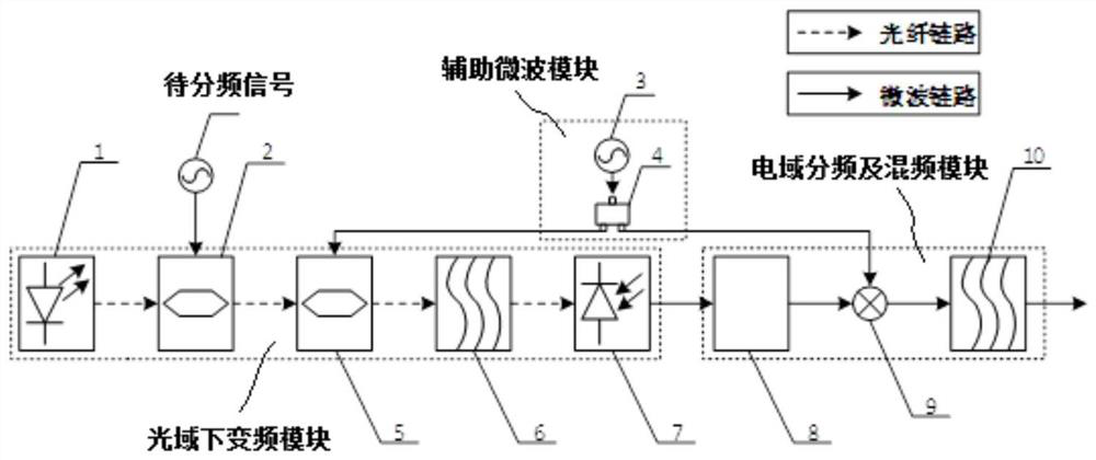
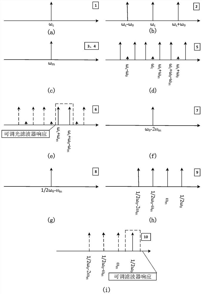
[0027] The present disclosure provides a microwave two-frequency divider based on microwave photonic technology. The microwave two-frequency divider based on microwave photonic technology uses microwave photonic technology to convert the signal to be divided into a relatively low-frequency frequency band in the optical domain. After frequency division by an electric frequency divider, a mixer and an adjustable filter, the two-frequency signal of the signal to be divided is finally obtained, and the frequency of the microwave signal output by the adjustable microwave source and the bandwidth of the adjustable filter are changed. The working frequency band of the frequency divider overcomes the difficulties of traditional electronic methods in terms of bandwidth, noise, power consumption, and electromagnetic compatibility.

[0028] In order to make the purpose, technical solutions and advantages of the present disclosure clearer, the present disclosure will be further described i...


PUM


Abstract

A microwave frequency divider based on microwave photon technology, including: an optical domain down-conversion module, which converts the signal to be divided into an electrical domain signal with a reduced angular frequency under the action of an auxiliary microwave signal; electrical domain frequency division and frequency mixing A module, connected to the optical domain down-conversion module, for halving the angular frequency of the electrical domain signal, and mixing with the auxiliary microwave signal to generate a frequency-division signal of the signal to be divided by two; and the auxiliary microwave module , one end is connected to the optical domain down-conversion module, and the other end is connected to the electrical domain frequency division and frequency mixing module, which is used to provide adjustable Auxiliary microwave signals are used to alleviate technical problems such as the narrow frequency division bandwidth of the analog frequency divider in the prior art, the low operating frequency of the digital frequency divider, and the high power consumption when increasing the maximum operating frequency of the circuit.

Description

technical field [0001] The present disclosure relates to the field of microwave photonics, in particular to a microwave frequency divider based on microwave photonic technology. Background technique [0002] With the rapid development of wireless communication systems and other related fields, more wireless communication standard protocols have been widely used. In order to meet the requirements of different protocol standards, the research and design of multi-mode communication systems have attracted more and more attention. In a multi-mode communication system, the frequency synthesizer used to provide a standard reference frequency for high precision and stability standards is the most important point in the entire design. For the frequency synthesizer, the frequency divider is a very important key module, which is related to the highest frequency and frequency range that the frequency synthesizer can work. [0003] Traditional frequency dividers based on electrical imp...

Claims


Application Information

Patent Timeline
Patent Type & Authority Patents(China)
IPC IPC(8): H03L7/18H04B10/516H04B10/54
CPCH03L7/18H04B10/516H04B10/5165H04B10/54
Inventor 杨成悟刘建国于文琦
Owner INST OF SEMICONDUCTORS - CHINESE ACAD OF SCI
Why Eureka
Try Eureka