Horizontal screw separating machine

A horizontal screw and mechanical technology, applied in the field of horizontal screw separation machinery, can solve problems such as inability to screen solid materials, and achieve the effect of eliminating cumbersome processes and strong practicability.

Inactive Publication Date: 2019-03-12
饶银娥
View PDF5 Cites 1 Cited by
  • Summary
  • Abstract
  • Description
  • Claims
  • Application Information

AI Technical Summary

Problems solved by technology

[0004] In order to overcome the deficiencies of the existing technology, a horizontal spiral separation machine is now proposed to solve the above-mentioned problems in the discharge of the horizontal spiral unloading sedimentation centrifuge composed of drums, screw pushers, motors and differentials. The problem that it is impossible to screen the solid material passing through the solid phase outlet, so as to achieve the effect of classifying and screening the solid material passing through the solid phase outlet

Method used


Image

  • Horizontal screw separating machine
  • Horizontal screw separating machine
  • Horizontal screw separating machine

Examples


Embodiment Construction

[0024] In this technical solution:

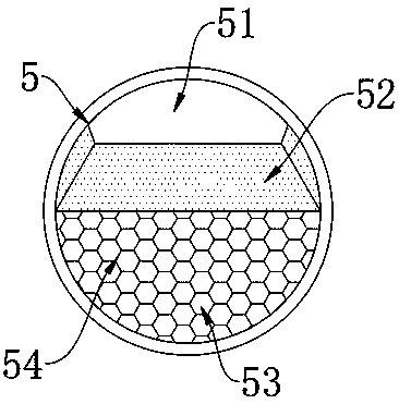
[0025] 51, 52, 53, and 54 are the substantive innovative components of the present invention.

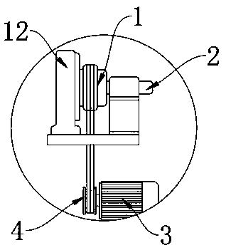
[0026] 1, 4, 9, 11, 12, and 13 are indispensable connecting components for realizing the technical solution of the present invention.

[0027] In order to make the object, technical solution and advantages of the present invention clearer, the present invention will be further described in detail below in conjunction with the accompanying drawings and embodiments. It should be understood that the specific embodiments described here are only used to explain the present invention, not to limit the present invention.

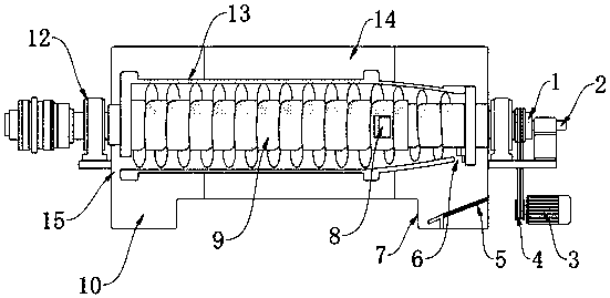
[0028] Such as figure 1 A kind of horizontal spiral separating machine shown, comprises casing 14 and rotating drum 13, and the inside of casing 14 is provided with rotating drum 13, and the peripheral edge of rotating drum 13 is movably connected in the inside of casing 14 by movable wheel, and rotating The inside of the drum 13 i...


PUM


Abstract

The invention discloses a horizontal screw separating machine. The horizontal screw separating machine comprises a shell cover and a barrate. The barrate is arranged in the shell cover. The circumferential edges of the barrate are movably connected into the shell cover by moving wheels. The barrate is internally provided with a screw pusher. The screw pusher is horizontally and transversely arranged in the barrate. Bearing seats are arranged at the left and right ends of the screw pusher. The bearing seats are arranged at the left and right ends of the shell cover. The left and right ends of the screw pusher are fixedly connected into the bearing seats by welding the outer surfaces of bearings. The bearing seats are connected with the left and right ends of the screw pusher in a sleeving mode. A material distributing device is arranged on the outer surface of the end, in the barrate, of the screw pusher. The material distributing device penetrates through the outer surface of one end of the screw pusher. In this way, material screening is achieved, and the problem of complex working procedures in subsequent screening is omitted. Convenience is achieved, and practicability is higher.

Description

technical field [0001] The invention relates to the technical field of separation machines, in particular to a horizontal spiral separation machine. Background technique [0002] The separation operation of substances is an operation process in which substances with different physical and chemical properties in a mixture are separated according to their different characteristics such as particle size, phase, density, solubility, boiling point, etc. Mechanical equipment that performs material separation operations is called separation machinery. Separation machinery is mainly used in chemical industry, pharmacy, light industry, petroleum, metallurgy, coal, dyestuff, food, brewing, papermaking and environmental protection departments. Separation generally uses methods such as filtration, distillation, recrystallization, extraction, centrifugation and adsorption. Contents of the invention [0003] (1) Technical problems to be solved [0004] In order to overcome the deficie...

Claims


Application Information

Patent Timeline
Patent Type & Authority Applications(China)
IPC IPC(8): B04B5/10
CPCB04B5/10
Inventor 饶银娥刘兆何广军
Owner 饶银娥
Why Eureka
Try Eureka