Portable anti-vibration multi-station universal rotary machining device

A rotary processing, anti-vibration technology, applied in metal processing equipment, metal processing mechanical parts, manufacturing tools, etc., can solve the problems of low processing efficiency, low processing and maintenance efficiency, difficult processing and use, etc., to achieve convenient use, disassembly and assembly. Convenience, reducing the effect of limitations

Pending Publication Date: 2019-03-12
罗甸县金泰模具机械制造有限公司
View PDF0 Cites 1 Cited by
  • Summary
  • Abstract
  • Description
  • Claims
  • Application Information

AI Technical Summary

Problems solved by technology

Existing milling machines are mainly of horizontal or vertical structure, which not only has a single function, but also has a large bed volume, and the processing stroke of the milling head is limited, so parts cannot be milled, bored, drilled, etc. It is difficult for a milling machine to process the slope of the workpiece, so for the processing of irregular parts, it often needs to be clamped multiple times or on a variety of machine tools. It can only be completed on a special machine tool, not only the operation is cumbersome, the processing efficiency is low, but the production cost is also high
The existing milling machine is difficult to disassemble and assemble the milling head. During the processing and production process, it is often shut down for maintenance due to the damage of the milling head.
Therefore, the existing milling machines have the disadvantages of large size, single function, cumbersome processing operations, difficult disassembly and assembly of the milling head, and low processing and maintenance efficiency.
[0003] The inventor invented such as: "portable three-axis rotary positioning universal milling machine", "magnetic rear pull rod positioning rotary universal milling machine", "shaft holding positioning rotary universal milling machine" and other small However, in the subsequent use, the inventor found that although the problem of adjusting the milling and drilling direction by the rotation of the milling head was solved, the positions of the milling head and the base of the machine tool were relatively fixed, and the position of the milling head during actual production and processing The connection method still has certain limitations, and the adjustment range of the processing position is limited. Especially when working in a small and narrow processing area, the base of the machine tool often becomes an important factor restricting the processing position of the washing head. This problem, however, cannot achieve the purpose of adjusting the direction of milling and drilling, and the disassembly and assembly of the extension rod is complicated, and it is difficult for the extension rod to be stably connected to the base of the machine tool, so it is still relatively difficult to process and use; Due to the vibration of the drill bit during the milling and drilling process, the bolts connecting the base and the column are likely to loosen, making the assembly of the column and the base unstable, which in turn affects the precision of milling and drilling
[0004] Therefore, the current milling machine has the problems of large volume of milling machine and single function of the milling head, while the connection mode of the milling head of the small universal milling machine is limited, the adjustment range of the machining position of the milling head is limited, and the connection stability of the connecting device is poor. The complex disassembly and assembly of the connector device makes it difficult to use the milling machine; there is also the problem that the connecting screws of the base and the column are easily loosened by vibration, resulting in unstable assembly of the column and the base, and the milling and drilling precision of the milling machine is not high.

Method used


Image

  • Portable anti-vibration multi-station universal rotary machining device
  • Portable anti-vibration multi-station universal rotary machining device
  • Portable anti-vibration multi-station universal rotary machining device

Examples


Embodiment Construction

[0031] The present invention will be further described below in conjunction with the accompanying drawings and embodiments, but not as a basis for limiting the present invention.

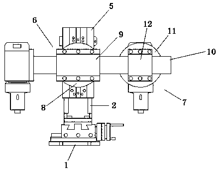
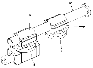
[0032] Example. Portable anti-vibration multi-station universal rotary processing device, such as Figure 1 to Figure 9 As shown, a base 1 is included, and a column 2 is arranged above the base 1, and the base 1 and the column 2 are connected through an anti-vibration device. The frame plate 4, the fixed seat 3 is connected with the fixed frame plate 4; a slider 5 is provided on one side of the column 2, and a rotary milling head device is arranged on the slider 5, and the rotary milling head device includes a The hoop rotation positioning device 6 and the hoop motor connection device 7; the hoop rotation positioning device 6 includes a positioning plate A8, a hoop connector A9 and a connecting shaft 10; the connecting shaft 10 passes through the hoop connector A9 is connected with the positioning d...


PUM


Abstract

The invention discloses a portable anti-vibration multi-station universal rotary machining device. The device comprises a base, wherein a stand column is arranged above the base, and the base is connected to the stand column through an anti-vibration device; the anti-vibration device comprises a fixing base and a fixing frame plate, wherein the fixing base is connected to the base, the fixing frame plate is arranged at the bottom of the stand column, and the fixing base is connected to the fixing frame plate; and a sliding block is arranged on one side of the stand column, and a rotary millinghead device is arranged on the sliding block. The device is small in size and convenient to carry, the machining angle and the milling head direction can be adjusted by 360 degrees in the X-axis direction and the Z-axis direction, the telescopic length of the milling head can be adjusted, the limitation of milling head connection is reduced, the working requirements of a narrow machining area aremet, so that the milling machine is more convenient to use, and the milling working efficiency is improved; and meanwhile, the stand column of the milling machine can be effectively prevented from vibrating in the milling and drilling process, connection screws of the base and the stand column are prevented from being easily loosened by vibration, so that the milling machine base and the stand column are connected more stably, and therefore the milling and drilling precision of the milling machine is improved.

Description

technical field [0001] The invention relates to a milling machine, in particular to a portable anti-vibration multi-station universal rotary processing device. Background technique [0002] Milling machine is an indispensable general-purpose equipment in the machinery manufacturing industry, and it is also a high-yield machine tool in the machine tool industry after the output of lathes. Existing milling machines are mainly of horizontal or vertical structure, which not only has a single function, but also has a large bed volume, and the processing stroke of the milling head is limited, so parts cannot be milled, bored, drilled, etc. It is difficult for a milling machine to process the slope of the workpiece, so for the processing of irregular parts, it often needs to be clamped multiple times or on a variety of machine tools. It can only be completed on a special machine tool, not only the operation is cumbersome, the processing efficiency is low, and the production cost i...

Claims


Application Information

Patent Timeline
Patent Type & Authority Applications(China)
IPC IPC(8): B23P23/02B23Q11/00B23Q1/26
CPCB23P23/02B23Q1/26B23Q11/0032
Inventor 刘海
Owner 罗甸县金泰模具机械制造有限公司
Why Eureka
Try Eureka