A design method of anti-sway bilge keel

A design method, the technology of the bilge keel, applied in the field of anti-rolling bilge keel design, can solve the problems of increased space and weight of equipment on board, increased ship design and construction costs, unsatisfactory anti-rolling effect, etc., to achieve reduction Occupies space and weight, reduces design and construction costs, and has the best anti-rolling effect

Active Publication Date: 2020-11-06
708TH RES INST OF CSSC
View PDF6 Cites 0 Cited by
  • Summary
  • Abstract
  • Description
  • Claims
  • Application Information

AI Technical Summary

Problems solved by technology

Although the bilge keel designed according to this method has a regular shape and is easy to process, its anti-rolling effect often cannot meet the overall design requirements of the ship, especially for ships with small square coefficients and ships with high requirements for rolling motion. It is necessary to install other types of anti-rolling devices, such as anti-rolling water tanks, passive or active anti-rolling fins, etc., which will not only increase the cost of ship design and construction, but also significantly increase the space and weight of the equipment on board

Method used


Image

  • A design method of anti-sway bilge keel
  • A design method of anti-sway bilge keel
  • A design method of anti-sway bilge keel

Examples


no. 1 example

[0045] The design method of the anti-rolling bilge keel of the first preferred embodiment, including:

[0046] Step S1: Determine the length L of the bilge keel according to the main dimension parameters of the target ship type and the characteristics of the hull shape BK and the layout range of the bilge keel along the ship's length direction (X-axis direction) [X start , X end ];

[0047] Step S2.1: Provide a cross-section diagram of the maximum cross-section of the target ship type, the cross-section diagram takes the direction of the ship's length as the direction of the abscissa axis (X-axis direction), and takes the direction of the ship's width as the direction of the ordinate-axis direction (Y-axis direction) ;

[0048] Step S2.2: Draw the frame angle of the maximum cross-section bounding box formed by the intersection of the bottom baseline or bilge rise line and the ship width margin line on the cross-section line diagram;

[0049] Step S2.3: Draw the height Z of t...

no. 2 example

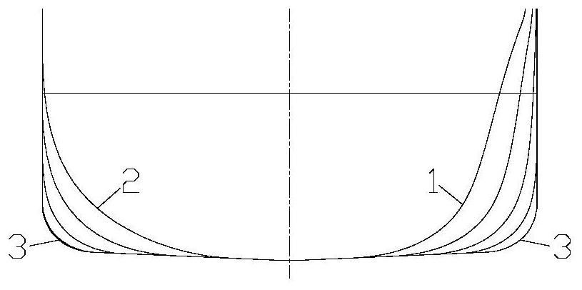
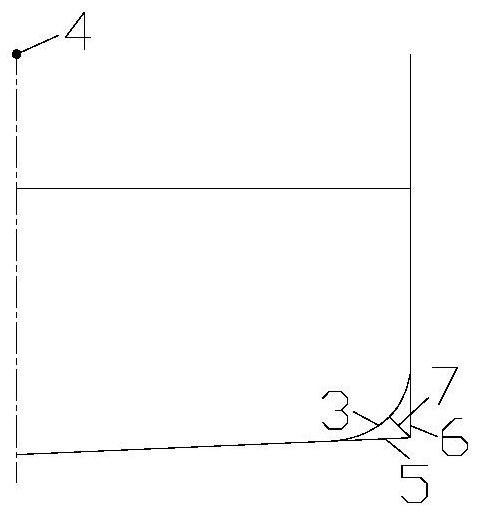
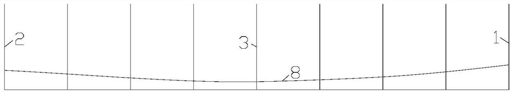
[0070] figure 1 It is the cross-sectional line diagram of the hull substations within the scope of the arrangement of the bilge keel along the length of the ship in the design method of the anti-rolling bilge keel of the present invention, figure 2 It is a schematic diagram of the maximum allowable width of the shape of the bilge keel at the maximum cross section of the anti-rolling bilge keel design method of the present invention, image 3 It is a side projection diagram of the installation line of the bilge keel on the hull of the design method of the anti-rolling bilge keel of the present invention, Figure 4 It is a schematic diagram of the maximum allowable width of the shape of the bilge keel at the transverse section line of a certain substation of the design method of the anti-rolling bilge keel of the present invention, Figure 5 It is a schematic diagram of the maximum allowable width limit line of the bilge keel shape and the maximum width limit line of the bilge...


PUM


Abstract

The invention discloses an anti-rolling bilge keel design method. The method comprises the steps that the length of a bilge keel and the arrangement range of the bilge keel in the ship length direction are determined; the mounting point and the shape maximum allowable width of the bilge keel are determined; a hull surface flow line which passes through the mounting point at the maximum transversesection and is located within the bilge keel arrangement range is determined to serve as a mounting line; hull transverse section lines of the multiple positions are cut out, the shape maximum allowable widths of all positions of the bilge keel are determined, and a shape maximum allowable width limit line of the bilge keel is drawn; the bilge keel structure maximum width is determined, and a structure maximum width limit line of the bilge keel is drawn; the parts, with the smaller width, of the shape maximum allowable width limit line and the structure maximum width limit line are selected for splicing, width gradient lines of the head end and the tail end of the bilge keel are designed, and a final bilge keel width limit line is obtained; structural design of the bilge keel is carried out. Accordingly, compared with a traditional method, the designed anti-rolling bilge keel has lager width, area and rolling damping.

Description

technical field [0001] The invention relates to the technical field of bilge keels, in particular to a method for designing a roll-stabilizing bilge keel. Background technique [0002] The bilge keel is a simple and effective anti-rolling device commonly used on ships, and its drag reduction effect mainly comes from the increase of roll damping. The length of the bilge keel has a certain effective range. Generally, the smaller the square coefficient of the ship, the smaller the effective length of the bilge keel. When the length of the bilge keel is determined, for safety reasons, the ship design community also requires that the width of the bilge keel should not exceed the bounding box of the maximum cross section. In this context, for a long time, the industry has formed a conventional method for designing the shape of the bilge keel, that is, firstly determine the effective length of the bilge keel according to the ship type, and then determine the effective length of th...

Claims


Application Information

Patent Timeline
Patent Type & Authority Patents(China)
IPC IPC(8): B63B71/00B63B71/20B63B39/06
CPCB63B39/06B63B71/00B63B3/44
Inventor 熊小青
Owner 708TH RES INST OF CSSC
Why Eureka
Try Eureka