
Method and system for detecting adjacent splicing mirrors

A detection method and imaging system technology, applied in the field of optics, can solve problems such as difficult splicing and alignment of splicing mirrors, and achieve the effects of convenient disassembly and maintenance, strong feasibility, and simple structure

Active Publication Date: 2019-03-12
CHANGCHUN INST OF OPTICS FINE MECHANICS & PHYSICS CHINESE ACAD OF SCI
View PDF11 Cites 2 Cited by
  • Summary
  • Abstract
  • Description
  • Claims
  • Application Information

AI Technical Summary

Problems solved by technology

[0005] Embodiments of the present invention provide a method and system for detecting adjacent splicing mirrors, so as to at least solve the technical problem of difficult splicing alignment of existing splicing mirrors

Method used


Image

  • Method and system for detecting adjacent splicing mirrors
  • Method and system for detecting adjacent splicing mirrors
  • Method and system for detecting adjacent splicing mirrors

Examples


Embodiment 1

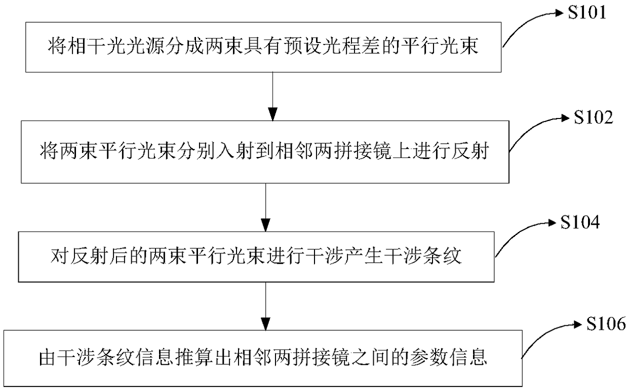
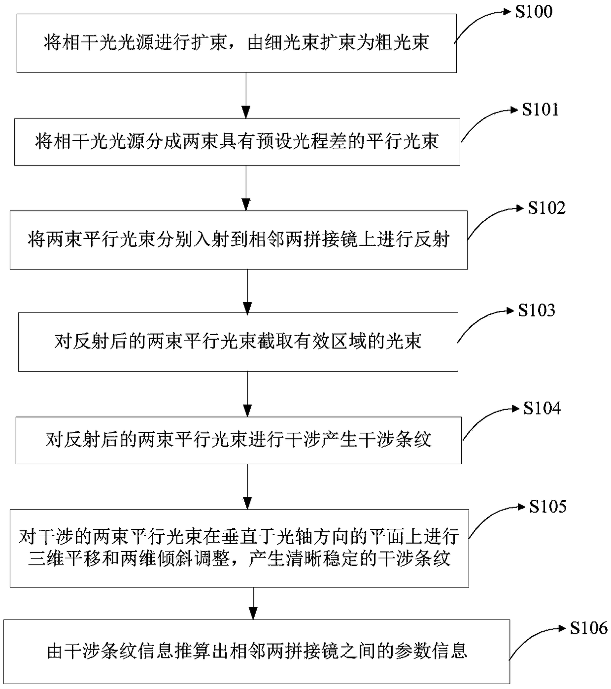
[0041] According to an embodiment of the present invention, a method for detecting adjacent spliced ​​mirrors is provided, which is suitable for confocal / co-phase of spliced ​​mirrors, see figure 1 , including the following steps:

[0042] S101: dividing the coherent light source into two parallel light beams with a preset optical path difference;

[0043] S102: the two parallel beams are respectively incident on two adjacent splicing mirrors for reflection;

[0044] S104: interfere with the reflected two parallel beams to generate interference fringes;

[0045] S106: Calculate the parameter information between two adjacent splicing mirrors from the interference fringe information.

[0046] In the method for detecting adjacent splicing mirrors in the embodiment of the present invention, the parameter information between two adjacent splicing mirrors is calculated from the interference fringe information, and the parameter information between the two adjacent splicing mirrors...

Embodiment 2

[0055] According to another embodiment of the present invention, see Figure 4 , provides an adjacent splicing mirror detection system, including:

[0056] Laser 1, used to generate a coherent light source;

[0057] a beam splitter, which is used for dividing the coherent light source into two parallel beams with a preset optical path difference and incident on two adjacent splicing mirrors for reflection;

[0058] The beam interferometer is used to generate interference fringes by interfering the reflected two parallel beams;

[0059] The parameter calculation unit is used to calculate the parameter information between two adjacent splicing mirrors from the interference fringe information.

[0060] As a preferred technical solution, the beam splitter includes: a right-angled triangular prism 3, a parallelogram prism 5, the right-angled triangular prism 3 is glued and connected with a parallelogram prism 5 whose angle is complementary to it, and the glue layer 4 realizes sem...


PUM


Abstract

The invention relates to the field of optics, in particular to a method and system for detecting adjacent splicing mirrors. According to the method and system, a coherent source is divided into two parallel beams with preset an optical path difference; the two parallel beams are emitted to two adjacent splicing mirrors respectively for reflection; the two reflected parallel beams are interfered togenerate interference fringes; parameter information between the adjacent two splicing mirrors is reckoned according to interference fringe information. Compared with an existing detection method adopting a edge sensor, the precision is higher, the detachment and maintenance are convenient, the method is not affected by environmental temperature, humidity, dust and other factors easily, operationis easy during assembly, the problem that the traditional edge sensor is easily affected by the environmental temperature, humidity, dust and other factors, and the method is suitable for the mirrorsurface of a splicing telescope needing high-precision confocal co-phase alignment; the structure is simple, the feasibility is strong, the installation is convenient, and the unit integration function is achieved.

Description

technical field [0001] The invention relates to the field of optics, and in particular, to a method and system for detecting adjacent splicing mirrors. Background technique [0002] In the application of deep space exploration, in order to observe more distant and fainter targets, it is necessary to continuously upgrade the diameter of the telescope. However, due to factors such as manufacturing, design risks, transportation and adjustment, the diameter of the telescope cannot be increased infinitely. At present, the diameter of the largest single telescope in the world is about 8.4m, and the optical system of the telescope with larger diameter can only be realized by means of sub-mirror splicing. For example, telescopes such as Keck, HET, and TMT, E-ELT, JWST, etc. that have been built are all in the form of splicing mirrors. [0003] The main feature of the splicing mirror of the splicing telescope is that each splicing mirror has three independent degrees of freedom (pis...

Claims


Application Information

Patent Timeline
Patent Type & Authority Applications(China)
IPC IPC(8): G01B11/24
CPCG01B11/2441
Inventor 安其昌曹海峰杨飞张景旭
Owner CHANGCHUN INST OF OPTICS FINE MECHANICS & PHYSICS CHINESE ACAD OF SCI
Learn More