Gun barrel strength testing device

A technology of strength testing and gun barrel, which is applied in production, civilian gun research, testing, and military fields. It can solve problems such as threatening the personal safety of testers, high chamber pressure at the moment of firing, and bursting of the main body of the receiver. It is simple, reliable, and easy to test. Improved safety and small footprint

Pending Publication Date: 2019-03-12
FUJIAN ORDNANCE EQUIP
View PDF0 Cites 2 Cited by
  • Summary
  • Abstract
  • Description
  • Claims
  • Application Information

AI Technical Summary

Problems solved by technology

[0003] Compared with ordinary bullets, the high-pressure bullets used in the test have more charge in the shell and higher chamber pressure at the moment of firing. Guns using this type of bullets for shooting are more prone to risk problems such as shell explosion, chamber explosion, and even bursting of the main body of the receiver. , similar test items always threaten the personal safety of testers
[0004] For the selection of this type of test timing, the industry generally installs the barrel to the receiver and conducts the strength test in the state of the assembled gun. Once the above-mentioned accidents occur, the entire gun will be scrapped at the same time in most cases, causing serious damage. The loss; and the shooting test requires at least 50 to 100 meters of closed safety target range, together with the construction, maintenance and management of supporting facilities and equipment, etc., resulting in a large area required for the test and a high test cost.

Method used


Image

  • Gun barrel strength testing device
  • Gun barrel strength testing device
  • Gun barrel strength testing device

Examples


Embodiment Construction

[0063] The following describes the patent of the present invention in detail with reference to the drawings. The following embodiments may enable those skilled in the art to better understand the patent of the present invention, but do not limit the patent of the present invention in any form.

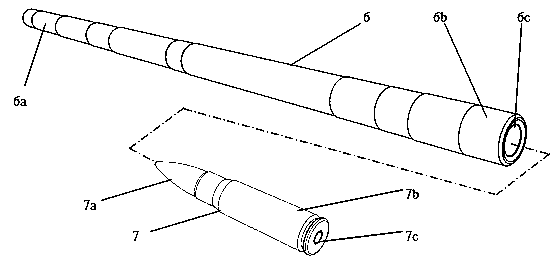
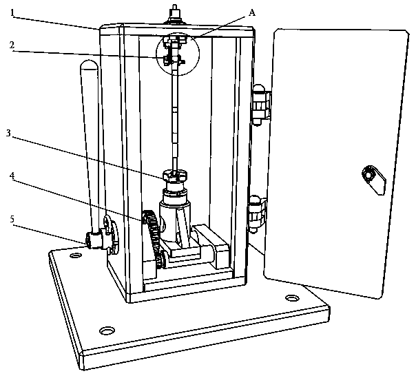
[0064] Such as figure 1 Shown is a schematic diagram of the barrel and bullet structure. Figure 2-38 As shown, it is a method for testing such as figure 1 The strength test device of the barrel shown is composed of a box assembly 1, a firing assembly 2, a base assembly 3, a locking assembly 4 and a driving rod assembly 5. The box body assembly 1 is composed of a box body 11 and a door panel 12. The box body 11 is five sides of a cube. The door panel 12 is hinged on the open side of the box body 11 to form a closed cube. The top of the box body 11 is machined with a firing mechanism installation hole 11a. , Used to install the firing assembly 2; the lower left side is machined with a drive...


PUM


Abstract

The invention relates to a gun barrel strength testing device which has the key point of consisting of a box body assembly, a firing assembly, a base assembly, a locking assembly and a driving rod assembly. A firing assembly interface is formed at the top end of the box body assembly; a base assembly interface is formed at the lower end of the box body assembly; a driving rod assembly interface isformed at the left side of the box body assembly; a firing assembly maim body is a base matched with a box body, a firing pin seat and a firing pin are arranged inside the firing assembly maim body,and a locking nut, a firing pin cover, a cushion block and a gun barrel buckle are mounted outside the firing assembly maim body; the base assembly is formed by connecting a lower base and a supporting seat, and a gun barrel seat is arranged on the base assembly; the locking assembly is supplied with supporting by an eccentric shaft seat, and a driving wheel is arranged on the locking assembly forcontrolling a pair of eccentric shafts to complete rotation to lift up the base assembly to lock a gun barrel; the driving rod assembly is formed by carrying out matching connection on a driving rodand a driving handle, is integrally inserted into the box body assembly and is used for driving the locking assembly to implement the locking action. The gun barrel strength testing device is ingenious in structure and convenient to operate; when a gun barrel strength testing effect is ensured, safety and working efficiency of testing can be improved, and testing cost is reduced.

Description

Technical field [0001] The invention patent relates to the fields of scientific research, production and testing of military and civilian guns. Background technique [0002] In the process of gun development, production, and testing, it is an indispensable link to carry out corresponding safety tests on guns. Among them, the relatively important item is the use of high-pressure test bullets to test the strength of the gun barrel when using the finished gun. Carry out assessment and verification to ensure that the safety of use after delivery meets the requirements. [0003] Compared with ordinary bullets, the test high-pressure bullets have more charge in the shell and higher chamber pressure at the moment of firing. The use of this type of ammunition for firearms is more prone to risk problems such as shell explosion, chamber explosion and even the main body explosion of the casing. , Similar test items always threaten the personal safety of testers. [0004] For the selection of ...

Claims


Application Information

Patent Timeline
Patent Type & Authority Applications(China)
IPC IPC(8): G01N3/313G01N3/02F41A31/02
CPCG01N3/313F41A31/02G01N3/02G01N2203/0274
Inventor 马玉石郑炳生王通黄国林宋有龙
Owner FUJIAN ORDNANCE EQUIP
Why Eureka
Try Eureka