Check patentability & draft patents in minutes with Patsnap Eureka AI!

optical system

An optical system and optical element technology, applied in the field of optical systems, can solve the problems of damage to the diffuser, increase in cost, decrease in light transmittance, etc., achieve good luminous efficiency and reliability, and avoid damage.

Active Publication Date: 2022-02-25
YOUNG OPTICS
View PDF11 Cites 0 Cited by
  • Summary
  • Abstract
  • Description
  • Claims
  • Application Information

AI Technical Summary

Problems solved by technology

However, under the structure of such a projector, it is necessary to add a diffuser to increase the overall cost of the projector, and the existence of the diffuser will also reduce the overall light transmittance
In addition, under the excitation beam with high energy density, there may be a risk of destroying the diffuser sheet.

Method used


Image

  • optical system
  • optical system
  • optical system

Examples


Embodiment Construction

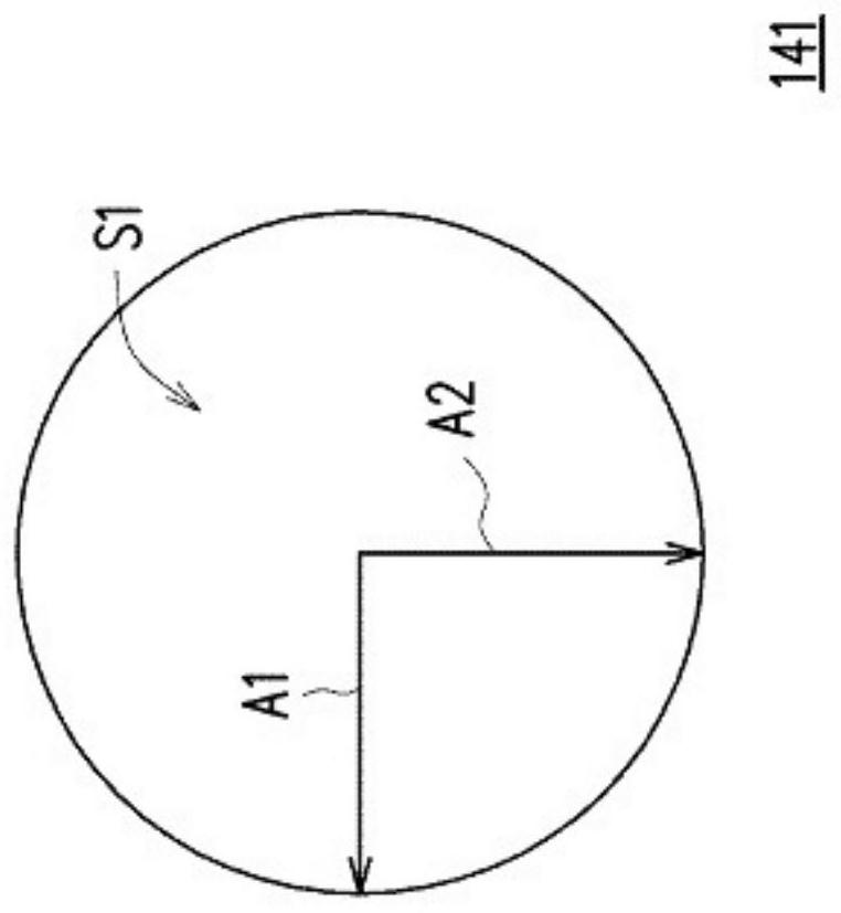
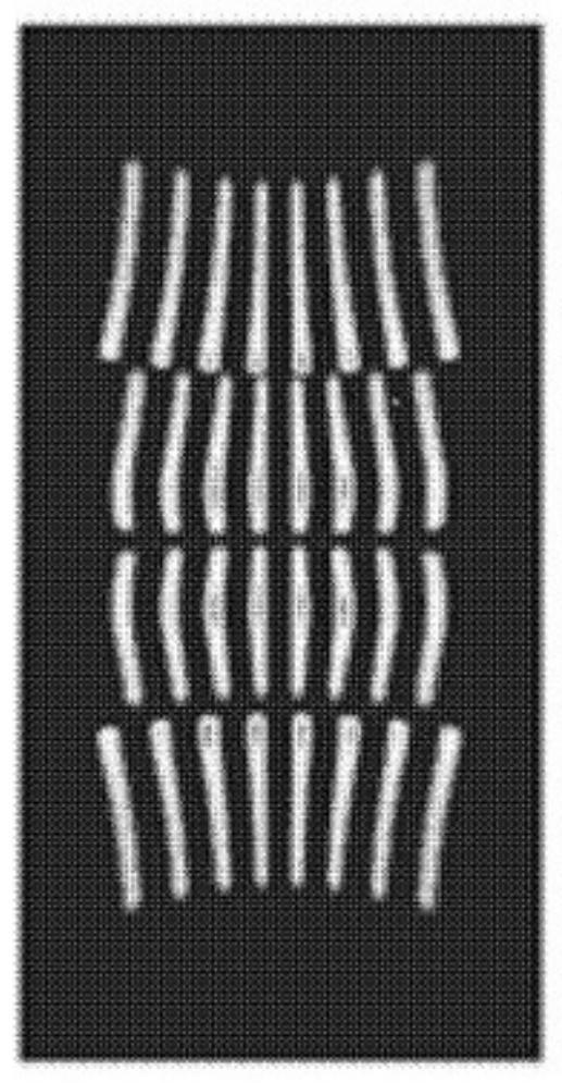
[0047] figure 1 It is a schematic structural diagram of an optical system according to an embodiment of the present invention. figure 2 shown as figure 1 Top view of the optical components of the optical system in. image 3 for the laser beam to pass through figure 1 The distribution diagram of the light spot matrix projected on the material layer by the optical elements of the optical system.

[0048] The optical element referred to in the present invention means that the optical element is made of partially or completely reflective or transmissive materials, usually consisting of glass or plastic.

[0049] Please refer to figure 1 , in this embodiment, the optical system 1 is a projector. The optical system 1 includes a light combining device 10 and an imaging device 20 . The light combining device 10 comprises a laser light source 110, a laser light source 120, a light combining element 130, an optical element 141, a lens group 150, a light splitting element 160, a l...


PUM

PropertyMeasurementUnit
wavelengthaaaaaaaaaa

Abstract

The invention provides an optical system, comprising a first laser light source capable of outputting a first laser beam, a first optical element and a first material layer. The first optical element is arranged on the optical path of the first laser light source. The first optical element has a first surface. The first axis and the second axis perpendicular to each other on the first surface have different curvature radii. The first material layer is arranged downstream of the optical path of the first optical element, and the first material layer contains photoluminescence material. Another optical system is also provided.

Description

technical field [0001] The invention relates to an optical system, in particular to an optical system suitable for a projector (Projector). Background technique [0002] With the development of solid-state light sources and projection technologies in recent years, projectors based on solid-state light sources such as Light Emitting Diodes (LEDs) and Laser Diodes (LDs) are gradually favored by the market. [0003] In an existing projector structure, the excitation beam emitted by the excitation light source is directly incident on the phosphor wheel (Phosphor Wheel), but this structure will cause the energy density of the phosphor wheel to be too high, which will affect the projector. Luminous efficiency and reliability (Reliability). [0004] In another conventional projector structure, the excitation light beam emitted by the excitation light source first enters the diffuser and then enters the fluorescent wheel. The diffusion sheet is used to scatter the excitation light...

Claims


Application Information

Patent Timeline
Patent Type & Authority Patents(China)
IPC IPC(8): G03B21/20G02B3/06G02B27/10
CPCG02B27/1006G03B21/204G03B21/208G02B3/06
Inventor 林经纶蔡威弘
Owner YOUNG OPTICS
Features
  • R&D
  • Intellectual Property
  • Life Sciences
  • Materials
  • Tech Scout
  • Unparalleled Data Quality
  • Higher Quality Content
  • 60% Fewer Hallucinations
Learn More