Same-frequency-band multi-target spatial separation method and device for unmanned aerial vehicle in urban environment

A space separation, urban environment technology, applied in wireless communication, electrical components, transmission systems, etc., can solve the problem of inability to suppress multipath interference, inapplicable to multiple target signal sources in the same frequency band, etc., to achieve the effect of suppressing multipath interference

Active Publication Date: 2019-03-12
河南宏泰控飞信息技术有限公司
View PDF14 Cites 0 Cited by
  • Summary
  • Abstract
  • Description
  • Claims
  • Application Information

AI Technical Summary

Problems solved by technology

[0004] The purpose of the present invention is to provide a method and device for spatial separation of multi-targets in the same frequency band of UAVs in an urban environment, to solve the problem that the existing detection UAVs cannot suppress multi-path interference and are not suitable for multi-targets in the same frequency band. signal source problem
[0005] In order to realize the separation of multi-target signals in the same frequency band of drones, solve the problem that the existing detection drones cannot suppress multi-path interference and are not suitable for multi-target signal sources in the same frequency band

Method used


Image

  • Same-frequency-band multi-target spatial separation method and device for unmanned aerial vehicle in urban environment
  • Same-frequency-band multi-target spatial separation method and device for unmanned aerial vehicle in urban environment
  • Same-frequency-band multi-target spatial separation method and device for unmanned aerial vehicle in urban environment

Examples


Embodiment Construction

[0048] The present invention will be described in further detail below in conjunction with the accompanying drawings.

[0049] Method example:

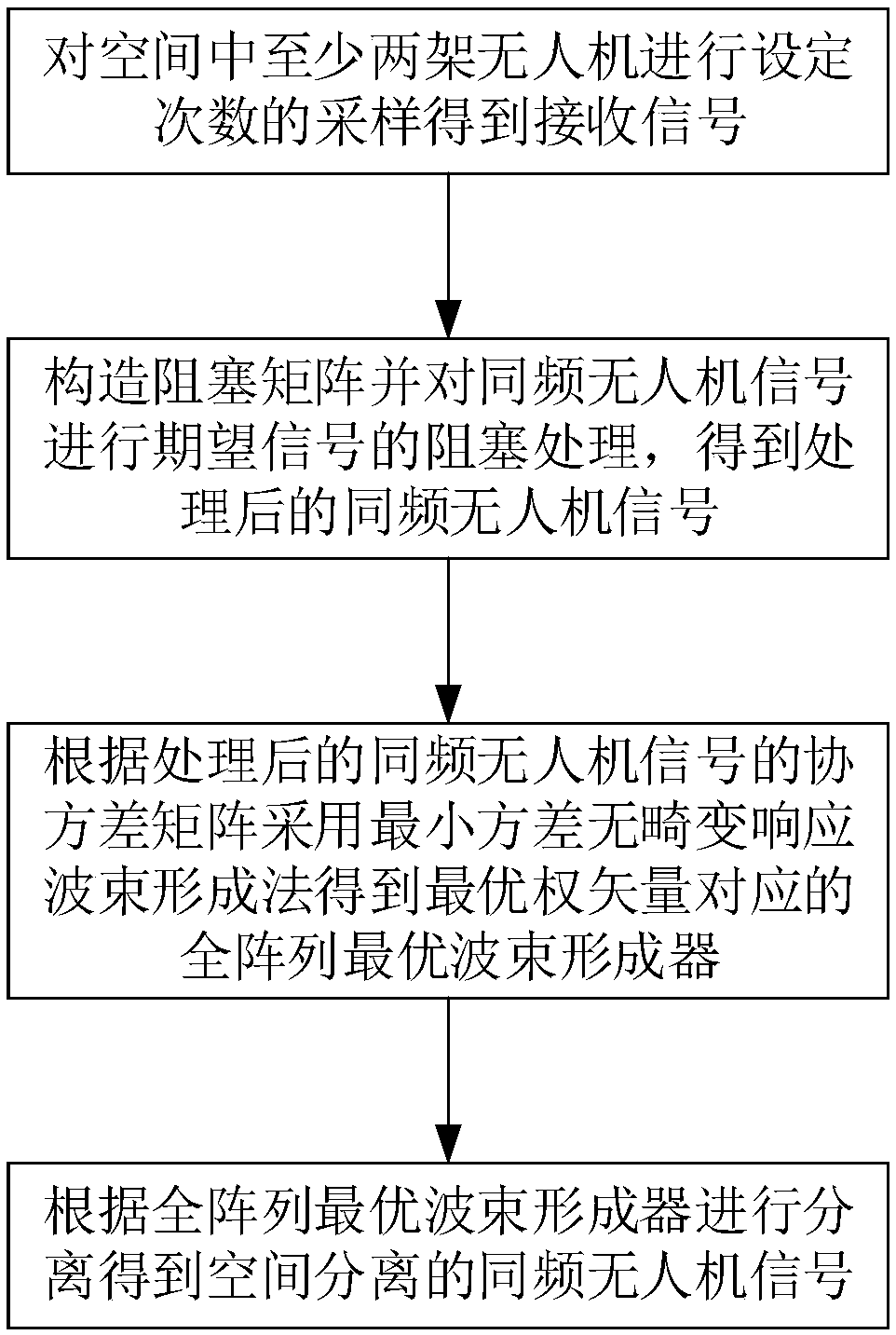
[0050] The present invention provides a method for spatially separating multiple objects in the same frequency band of UAVs in an urban environment, such as figure 1 shown, including the following steps:

[0051] 1) Sampling at least two drones in the space for a set number of times to obtain received signals.

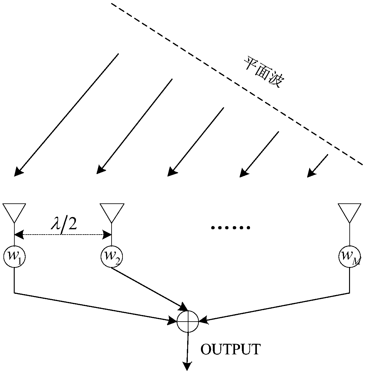
[0052] Arrange multi-channel digital uniform linear array equipment to perform multi-snapshot sampling of multiple UAV signals in space, such as figure 2 As shown, the number of array elements arranged in the multi-channel digital uniform linear array device is M, and the array element spacing is d. The array element spacing used in the present invention is half a wavelength, and is output through OUTPUT.

[0053] A multi-channel digital uniform linear array device is used to sample at least two UAVs in the space for a set...


PUM


Abstract

The invention relates to the technical field of unmanned aerial vehicle control, in particular to a same-frequency-band multi-target spatial separation method and device for an unmanned aerial vehiclein an urban environment. The method comprises the following steps of sampling at least two unmanned aerial vehicles in the space for a set number of times to obtain a received signal; when a coherentsame-frequency unmanned aerial vehicle signal exists in the received signal, constructing a blocking matrix, and carrying out blocking processing of a desired signal on the same-frequency unmanned aerial vehicle signal in order to obtain a processed same-frequency unmanned aerial vehicle signal; and obtaining a full-array optimal beam former by adopting a beam forming method according to a covariance matrix of the processed same-frequency unmanned aerial vehicle signal, and carrying out separation according to the full-array optimal beam former corresponding to an optimal weight vector in order to obtain the spatially separated same-frequency unmanned aerial vehicle signal. The blocking processing is carried out on the same-frequency coherent signal through the constructed blocking matrix, the desired signal is filtered out, and multi-path interference is inhibited; and meanwhile, the processed signal is recovered through the full-array wave beam forming in order to realize the separation of the same-frequency-band multi-target signal, and the method and the device are applicable to unmanned aerial vehicle reconnaissance operations in the presence of a same-frequency-band multi-target signal source.

Description

technical field [0001] The invention relates to the technical field of unmanned aerial vehicle control, in particular to a method and device for spatially separating multiple targets in the same frequency band of an unmanned aerial vehicle in an urban environment. Background technique [0002] In UAV swarm combat, UAV signals generally adopt the form of code division multiple access, and there are multiple target signals in the same frequency band. In addition, in the urban environment, the reflection of signals by buildings, etc. causes multipath effects, which leads to the correlation or even coherence between the expected signal and interference in reconnaissance. These factors have a negative impact on the detection and identification of UAVs. [0003] Existing UAV detection devices mostly use amplitude ratio method and interferometer direction finding. These two systems cannot handle multiple UAV signals in the same frequency band or similar frequency bands at the same ...

Claims


Application Information

Patent Timeline
Patent Type & Authority Applications(China)
IPC IPC(8): H04B15/00H04W16/28
CPCH04B15/00H04W16/28
Inventor 杜绍岩杨纳川王永华邵佳袁航牛原野张宝山魏峰
Owner 河南宏泰控飞信息技术有限公司
Why Eureka
Try Eureka