
Construction method of T-shaped capping beam

A construction method and technology for covering beams, applied in bridges, bridge materials, bridge construction, etc., can solve the problem of reducing the overall stability and load-bearing capacity of brackets, cannot adjust the height of I-steel brackets, and cannot solve the difficulties in the construction of T-shaped cover beams. and other issues to achieve the effect of improving stability and load-bearing capacity, improving overall stability, and preventing sliding

Inactive Publication Date: 2019-03-15
GUANGXI ROAD & BRIDGE ENG GRP CO LTD
View PDF9 Cites 5 Cited by
  • Summary
  • Abstract
  • Description
  • Claims
  • Application Information

AI Technical Summary

Problems solved by technology

Yet the construction bracket of its bridge cover girder also has the following problems in use: 1, the top plate of finish-rolled threaded steel bar (4) and steel plate bracket (5) is spaced apart, and during use, the pressure that bracket is subjected to passes through The side wall of the hole is transmitted to the finish-rolled threaded steel bar (4), and its action surface is only the part where the finished-rolled threaded bar 500 (4) is in contact with the side wall of the through hole, and the stress is relatively concentrated, which reduces the overall stability and load-bearing of the bracket ability
2. The side plates on both sides of the steel plate bracket (5) are prone to deformation when subjected to pressure, which reduces the life of the steel plate bracket (5) and affects the quality of the cover beam; 3. The fine-rolled threaded steel bar (4) passes through the steel plate bracket After the through hole of the frame (5), it is fixedly connected with the steel plate bracket (5) through the nut (6). The construction bracket of the beam cannot adjust the height of the I-beam bracket, which is not conducive to the formwork construction and the subsequent dismantling of the seat; technical issues
[0004] Chinese invention patent application CN107100076A discloses a construction method for cast-in-place cap beams, which uses hoops installed at appropriate positions on the pier columns and clamps them with the pier columns to generate friction to overcome the weight of the facilities and the cap girder. However, The hoop bracket is easy to slide down, resulting in poor security

Method used


Image

  • Construction method of T-shaped capping beam
  • Construction method of T-shaped capping beam
  • Construction method of T-shaped capping beam

Examples


Embodiment Construction

[0038] The following will clearly and completely describe the technical solutions in the embodiments of the present invention with reference to the accompanying drawings in the embodiments of the present invention. Obviously, the described embodiments are only some, not all, embodiments of the present invention. Based on the embodiments of the present invention, all other embodiments obtained by persons of ordinary skill in the art without making creative efforts belong to the protection scope of the present invention.

[0039] It should be noted that when a component is said to be "fixed" to another component, it can be directly on the other component or there can also be an intervening component. When a component is said to be "connected" to another component, it may be directly connected to the other component or there may be intervening components at the same time. When a component is said to be "set on" another component, it may be set directly on the other component or t...


PUM


Abstract

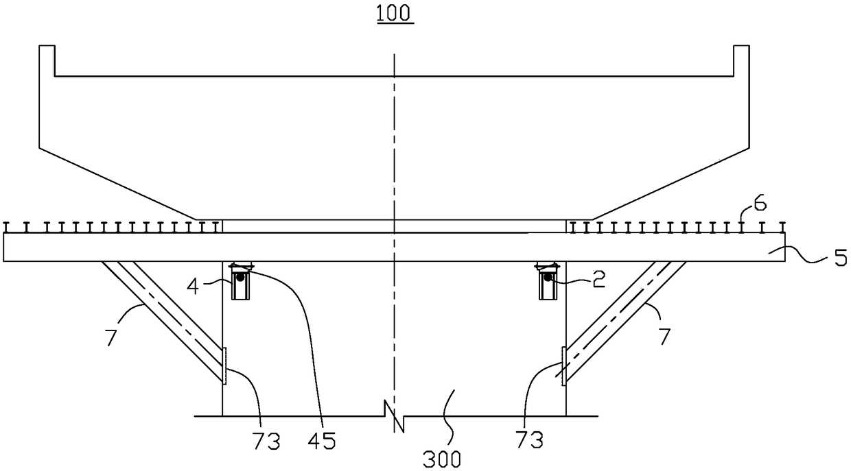
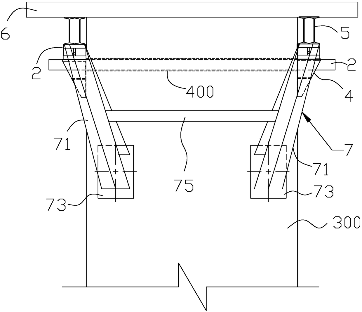
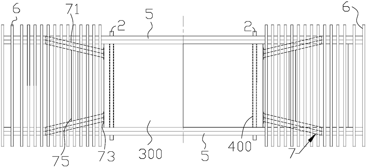
The invention provides a construction method of a T-shaped capping beam. The method comprises the steps of pre-burying of a pre-buried piece on a bridge pier, steel bar installing, stand installing, installing of a sizing block device, installing of a bearing beam, installing of a distributive girder, installing of an oblique leg supporting frame and installing of a template. The steel bar and thestand sleeving the steel bar are utilized for supporting the bearing beam, two oblique leg supporting frames arranged on the two opposite sides of the bridge pier in the direction perpendicular to the steel bar are utilized for supporting a suspending part, located outside the bridge pier, of the bearing beam, supporting points of a template bearing frame are increased, so that the stability andstrength of the template bearing frame of the capping beam are improved, and the method is suitable for construction of the T-shaped capping beam.

Description

technical field [0001] The invention relates to the technical field of cover beam construction, in particular to a T-shaped cover beam construction method. Background technique [0002] The cover beam is a very important part of the bridge. During construction, the assembly of the formwork greatly affects the quality of the cover beam. In the prior art, the formwork is usually built on the bracket device. Among them, the T-shaped cover beam has higher requirements on the strength and stability of the bracket device due to the larger length of the cantilever protruding from the pier. [0003] Chinese invention patent application CN102277834A discloses a construction bracket for a bridge cover beam, which includes a finish-rolled threaded steel bar (4) that runs through a bridge column (1), and is arranged on A steel plate bracket (5) on both ends of the column (1) and an I-shaped steel bracket (7) supported by the steel plate bracket (5). The steel plate bracket (5) is the...

Claims


Application Information

Patent Timeline
Patent Type & Authority Applications(China)
IPC IPC(8): E01D21/00
CPCE01D21/00E01D2101/268
Inventor 李莘哲周妤莲江鑫泰覃勇然魏华王振琦吕中玉李雪芬曹杨王楚杰
Owner GUANGXI ROAD & BRIDGE ENG GRP CO LTD
Learn More