
Positioning and rectification device for pile body reinforcing bar cage

A technology of correction device and steel cage, which is applied in sheet pile wall, construction, infrastructure engineering and other directions, can solve the problems of increasing the danger of workers, increasing the workload of workers, and increasing the sediment at the bottom of the pile, so as to reduce the construction risk and reduce the Worker workload and cost reduction effect

Inactive Publication Date: 2019-03-15
CCCC SHEC FIRST HIGHWAY ENG
View PDF0 Cites 0 Cited by
  • Summary
  • Abstract
  • Description
  • Claims
  • Application Information

AI Technical Summary

Problems solved by technology

[0006] The purpose of the present invention is to provide a positioning and deviation correction device for the reinforcement cage of the pile body, so as to solve the above-mentioned background technology when the reinforcement cage is lowered, the reinforcement cage will scratch the pile hole wall, and the soil on the pile hole wall will be easily scratched. Increase the pile bottom sediment, increase the workload of workers, and the pile hole is generally deep, it is not easy to clean the sediment, which increases the danger of workers when working; and it is difficult to ensure that the reinforcement cage is concentric with the pile hole, which increases the workload.

Method used

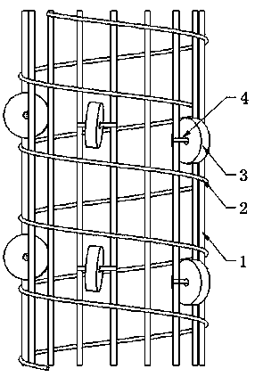

Image

  • Positioning and rectification device for pile body reinforcing bar cage
  • Positioning and rectification device for pile body reinforcing bar cage
  • Positioning and rectification device for pile body reinforcing bar cage

Examples


Embodiment 1

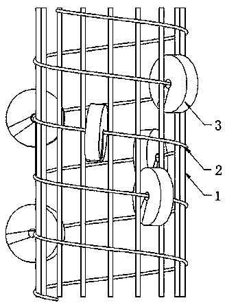
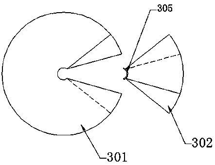
[0034] According to the engineering requirements, drill the pile holes, prefabricate the reinforcement cage, prefabricate the annular pad 3 according to the required thickness of the reinforced concrete protective layer, and then according to the depth of the pile hole, place stirrups of the same section every two meters along the length direction of the main reinforcement 1 2 is provided with a group of annular pads 3, the number of each group of annular pads 3 is greater than 3 and is evenly arranged on the stirrup 2 along the circumferential direction, generally each group uses 4 annular pads 3; open the small fan-shaped pads 302 Put the large sector pad 301 on the stirrup 2, and insert the small sector pad 302 according to the staggered meshing direction of the team until the limit rubber block 305 is reset to realize the positioning of the large sector pad 301 and the small sector pad 302 ;

[0035] When the reinforcement cage is hoisted by the hoist and ready to be lower...

Embodiment 2

[0037] The structure of the simple annular cushion block involved in the present invention, under the condition that other structures remain unchanged, can be that the stopper rubber block 305 realizing the radial limit function consists of two steps of the large sector-shaped cushion block 301 and the small sector-shaped cushion block 302 The positioning holes that cooperate with each other are set on the surface and the concave surface instead, and then the radial limit function is realized through bolt connection.

[0038] To sum up, through the improvement of the ring-shaped block of the existing steel cage structure, a pile body steel cage positioning and deviation correction device has the function of conveniently inserting the stirrup and rolling the steel cage down, thereby reducing the impact on the pile. Scratching of the hole wall reduces the cost, reduces the workload of workers and reduces the risk of construction.


PUM


Abstract

The invention relates to the technical field of building construction, in particular to a positioning and rectification device for a pile body reinforcing bar cage. An annular cushion block comprisesa large fan-shaped cushion block and a small fan-shaped cushion block matched with the large fan-shaped cushion block. The large fan-shaped cushion block and the small fan-shaped cushion block can bematched to form a complete annular cushion block, and the mating joint of the large fan-shaped cushion block and the small fan-shaped cushion block is provided with mutually matched steps, and a limiting rubber block is arranged at the small arc surface of the small fan-shaped cushion block. The positioning and rectification device for the pile body reinforcing bar cage has the beneficial effectsthat by improving the annular cushion block of the existing reinforcing bar cage structure, the annular cushion block used for reducing the rubbing against the hole wall of a pile hole in the reinforcing bar cage structure has the functions of conveniently inserting a stirrup and rolling down a reinforcing bar cage, thereby obtaining the effects of reducing the rubbing against the hole wall of thepile hole, reducing the cost, reducing the workload of the workers and reducing the construction risk.

Description

technical field [0001] The invention relates to the technical field of building construction, in particular to a positioning and deviation correcting device for a reinforcement cage of a pile body. Background technique [0002] In building construction technology, the compressive strength of concrete is high but the tensile strength is very low. When the concrete structure is a columnar or strip member, in order to improve the tensile effect, the central part does not need reinforcement, and only when the concrete member contacts Reinforcement is placed under the surface of the air; we prefabricate the reinforcement around this component, usually we call the prefabricated reinforcement structure such as bored pile, digging pile, column and so on, a reinforcement cage, which constrains the concrete of the pile body function, so that it can withstand a certain horizontal force; during construction, piling is carried out according to requirements, the method is to use machine p...

Claims


Application Information

Patent Timeline
Patent Type & Authority Applications(China)
IPC IPC(8): E02D5/34
CPCE02D5/34
Inventor 沈燕飞谢宇刘晓雨潘君贝
Owner CCCC SHEC FIRST HIGHWAY ENG
Learn More