
Large-capacity ultra-high-speed optical fiber sensing device for spacecraft strain monitoring

A technology of optical fiber sensing and optical fiber sensor, which is used in measurement devices, optical devices, instruments, etc., can solve the problems of complex lines, increased failure rate, and difficulty in meeting the needs of large-capacity optical fiber sensing arrangements for spacecraft.

Active Publication Date: 2019-03-15
SHANDONG INST OF AEROSPACE ELECTRONICS TECH
View PDF9 Cites 2 Cited by
  • Summary
  • Abstract
  • Description
  • Claims
  • Application Information

AI Technical Summary

Problems solved by technology

[0006] But at present, the best technical state of my country's fiber grating sensing technology on spacecraft is that "the number of single optical fiber sensors is less than 10, and the demodulation rate is lower than 5kHz"
In particular, the key technology of "high sensor count per fiber" and "ultra-fast demodulation rate" has not yet been resolved, which will have a great impact on subsequent function expansion applications
[0007] On the one hand, it is difficult to meet the needs of large-capacity optical fiber sensing arrangements for spacecraft in large areas
If it is necessary to arrange optical fiber sensors in a large area, dozens to hundreds of optical fibers are required, the wiring will be more complicated, the failure rate will increase, and the weight cost will increase significantly
[0008] On the other hand, the demodulation speed is low, and it is impossible to monitor high-frequency strain and vibration signals higher than 5kHz, such as the high-frequency signals generated by the debris impact process, which seriously limits the functional expansion of optical fiber sensing on spacecraft and widely used

Method used


Image

  • Large-capacity ultra-high-speed optical fiber sensing device for spacecraft strain monitoring
  • Large-capacity ultra-high-speed optical fiber sensing device for spacecraft strain monitoring
  • Large-capacity ultra-high-speed optical fiber sensing device for spacecraft strain monitoring

Examples


Embodiment Construction

[0034] The present invention will be described in detail below with reference to the accompanying drawings and embodiments.

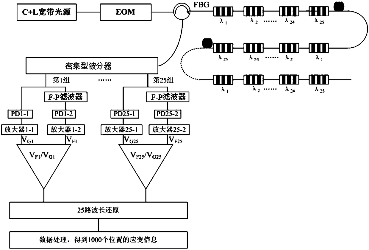
[0035] like figure 1 As shown, the large-capacity ultra-high-speed optical fiber sensing device of the present invention includes a C-band+L-band continuous broadband light source, an electro-optical modulator EOM, a circulator, 40 groups of optical fiber sensors, a dense wavelength divider, a voltage proportional module, and a wavelength reduction module. and the strain acquisition module;

[0036] The wavelength range of C-band + L-band continuous broadband light source is 1520-1610nm, the bandwidth is 90nm, the power is not less than 20dBm, and the spectral flatness is less than 2dB.

[0037] The electro-optical modulator EOM is operated by the drive circuit to open and close the optical path of the EOM. The drive circuit obtains the signal from the function generator. The pulse signal period given by the function generator is 10μs and the pulse wid...


PUM

PropertyMeasurementUnit
Poweraaaaaaaaaa
Isolationaaaaaaaaaa

Abstract

The invention discloses a large-capacity ultra-high-speed optical fiber sensing device for spacecraft strain monitoring. The device solves the technical problem of simultaneously having 'large numberof sensors of single fiber' and 'ultra-fast demodulation rate'; a novel sensing framework is constructed, a 'dense splitting technology' and a 'low-reflectivity grating alternate use technology' are adopted to increase the capacity of the sensors on a single fiber, the number of the sensors of the single fiber is larger than one thousand, and the demands for large-area-array detection of the large-capacity optical fiber of a spacecraft are met; the ultra-high-speed demodulation of optical fiber sensing of the spacecraft is achieved through a non-mechanical strength adjustment principle, related research achieves upgrading of existing products, and great market value is brought.

Description

technical field [0001] The invention belongs to the technical field of optical fiber sensing, in particular to a large-capacity ultra-high-speed optical fiber sensing device used for spacecraft strain monitoring. Background technique [0002] During the spacecraft's in-orbit flight, debris and particles in space will collide with the spacecraft at a high speed. These collisions will cause strain on the surface of the spacecraft cabin, resulting in damage accumulation. At the same time, the capsule will also be deformed during the process of pressure filling and decompression and rendezvous and docking of the spacecraft. Therefore, it is necessary to monitor the strain of the spacecraft cabin in real time, which will provide a guarantee for the reliability and safety of the spacecraft. [0003] At present, two methods of piezoelectric sensors and fiber grating sensors are mainly used to monitor the strain of spacecraft cabins. [0004] (1) Piezoelectric sensors. Due to the...

Claims


Application Information

Patent Timeline
IPC IPC(8): G01B11/16
CPCG01B11/165
Inventor 罗玉祥邵飞郭春辉申景诗王帅张建德王翀
Owner SHANDONG INST OF AEROSPACE ELECTRONICS TECH
Learn More