
A Bionic Lateral Flow Sensor

A flow sensor and sensor technology, applied in the field of sensors, can solve problems such as differences in the biological structure of the fish lateral line, and achieve the effects of compact structure, reasonable layout, and fluid velocity sensitivity

Active Publication Date: 2020-04-03
烟台易尚电子科技有限公司
View PDF8 Cites 0 Cited by
  • Summary
  • Abstract
  • Description
  • Claims
  • Application Information

AI Technical Summary

Problems solved by technology

It can be seen that the structure of the existing bionic lateral line sensor is still slightly different from the biological structure of the actual fish lateral line

Method used


Image

  • A Bionic Lateral Flow Sensor
  • A Bionic Lateral Flow Sensor
  • A Bionic Lateral Flow Sensor

Examples


Embodiment Construction

[0025] The following will clearly and completely describe the technical solutions in the embodiments of the present invention with reference to the accompanying drawings in the embodiments of the present invention. Obviously, the described embodiments are only some, not all, embodiments of the present invention. Based on the embodiments of the present invention, all other embodiments obtained by persons of ordinary skill in the art without making creative efforts belong to the protection scope of the present invention.

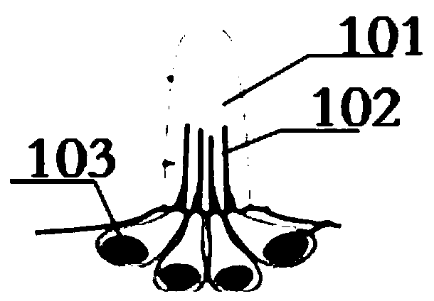
[0026] The purpose of the present invention is to provide a bionic lateral flow sensor which is easy to install, has an integrated design, and has a structure closer to the neuromast, the lateral line perception unit of fish.

[0027] In order to make the above objects, features and advantages of the present invention more comprehensible, the present invention will be further described in detail below in conjunction with the accompanying drawings and specific e...


PUM


Abstract

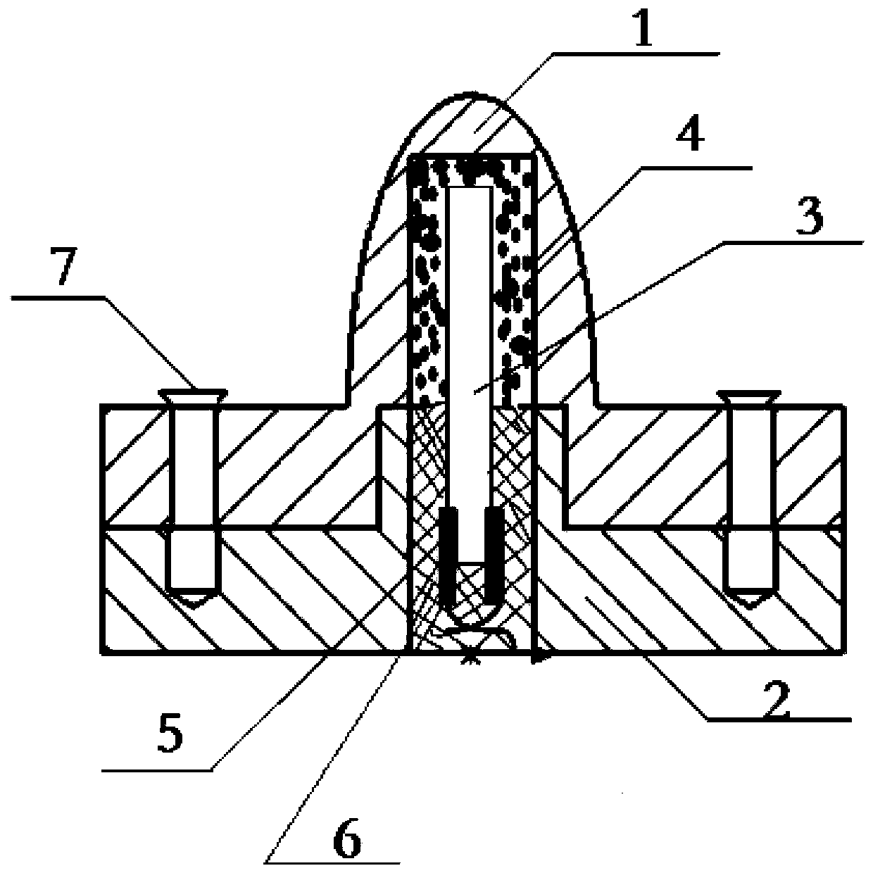
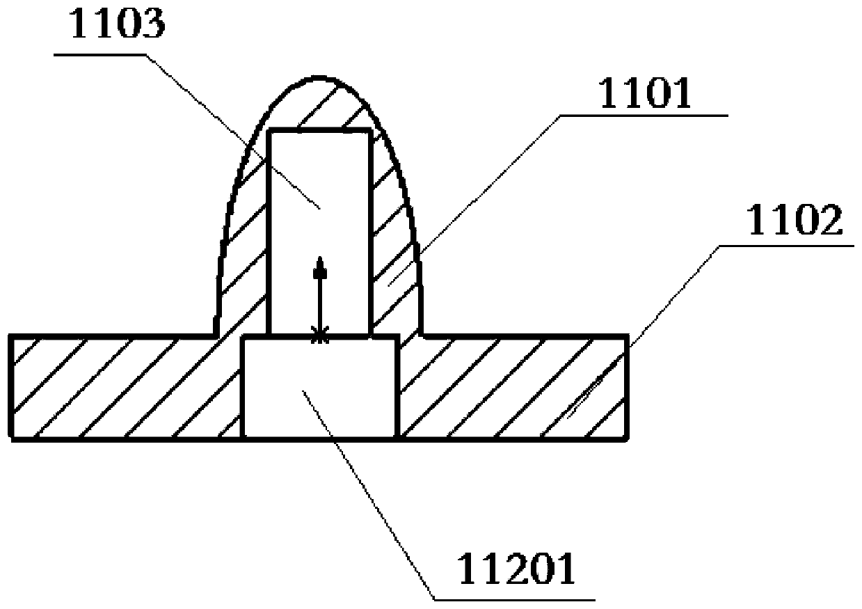
The invention discloses a bionic lateral line flow sensor. The sensor comprises a colloid top, a sensor shell and a polyvinylidene fluoride piezoelectric thin film; the colloid top comprises a top part of the colloid top and a first cylinder, the top part of the colloid top is located on the first cylinder, and the bottom area of the top part of the colloid top is smaller than that of the bottom face of the first cylinder; a first groove is formed in the bottom of the first cylinder, a second groove is formed in the bottom of the colloid top, the bottom area of the second groove is smaller than that of the first groove, and the first groove is communicated with the second groove; the sensor shell comprises a second cylinder shell and a protrusion, the protrusion is arranged on the top faceof the second cylinder shell, the size of the protrusion is matched with that of the first groove, and the sensor shell is fixedly connected with the colloid top; one end of the polyvinylidene fluoride piezoelectric thin film is inserted in the protrusion, and the other end of the polyvinylidene fluoride piezoelectric thin film is inserted in the second groove. The sensor is integrally designed and is convenient to install, and the structure is closer to a lateral line sensing unit for fishes.

Description

technical field [0001] The invention relates to the field of sensors, in particular to a bionic lateral flow sensor. Background technique [0002] Current sensors can be divided into mechanical propeller type, electromagnetic type, acoustic type and optical type according to the principle. Typical measuring instruments such as Uckmann current meter, S4 electromagnetic current meter produced by Interocean in the United States, and 2-D type by Falmouth Scientific Company Transit-time acoustic current meter, Norway's Andrei current meter RCM-9 (Doppler acoustic current meter) and acoustic Doppler current profiler, particle imaging velocimeter PIV and so on. These meters have their own advantages and disadvantages. For example, the accuracy of the acoustic sensor will be affected by seawater temperature, salinity, suspended particles, acoustic scattering and multipath propagation, etc.; the accuracy of the optical sensor will be affected. Effect of sea turbidity. Furthermore, ...

Claims


Application Information

Patent Timeline
Patent Type & Authority Patents(China)
IPC IPC(8): G01D5/14
CPCG01D5/14
Inventor 谈世哲刘渊魏新民谈博文
Owner 烟台易尚电子科技有限公司
Learn More