
Winding follow-up pinch roller device for thin-film capacitor winding machine

A technology for film capacitors and winding machines, which is used in winding capacitor machines and other directions to achieve the effects of reducing friction, improving quality stability, and improving work stability

Active Publication Date: 2019-03-15
CHANGZHOU SAVY MACHINE
View PDF6 Cites 0 Cited by
  • Summary
  • Abstract
  • Description
  • Claims
  • Application Information

AI Technical Summary

Problems solved by technology

[0005] The purpose of the present invention is to overcome the shortcomings of the existing film capacitor winding machine winding pressure wheel device that affects the film winding quality due to changes in the pressure and pressure direction during the working process, and to provide a film capacitor winding machine winding Follow the pressure roller device, adopt the technical solution of the present invention, use the angle sensor to detect the swing angle of the pressure roller during the metal film winding process in real time, and control the pressure roller to follow the backward movement with the increase of the diameter of the metal film roll through the detected swing angle signal, At the same time, the low-friction cylinder is used to control the pressure of the pressure roller on the metal film roll, so that the pressure direction and size of the pressure wheel on the metal film roll will not change greatly with the change of the winding diameter, and the air guide mechanism and the pressure wheel are used The mechanism follows, so that the distance between the air conduction mechanism and the winding mechanism changes little, so that the metal film can be wound smoothly, and the quality stability of the film capacitor is improved.

Method used


Image

  • Winding follow-up pinch roller device for thin-film capacitor winding machine
  • Winding follow-up pinch roller device for thin-film capacitor winding machine
  • Winding follow-up pinch roller device for thin-film capacitor winding machine

Examples


Embodiment

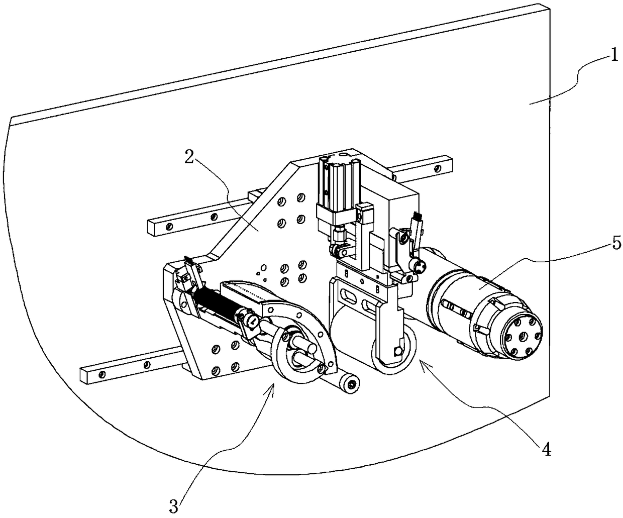
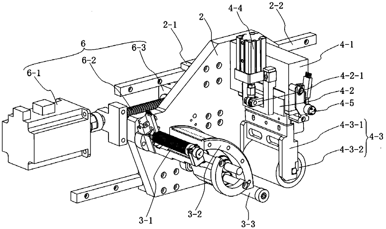
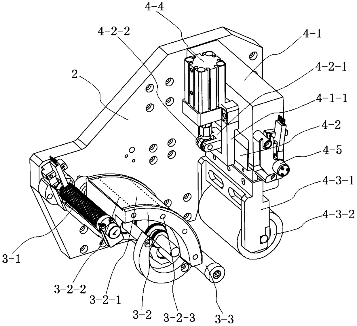
[0037] combine Figure 1 to Figure 5 As shown, a film capacitor winding machine of this embodiment is rewinding and following the pressure wheel device, which is installed on the substrate 1 and is located near the rewinding mechanism 5. The rewinding mechanism 5 in this embodiment can use existing materials The disk fixture is used to clamp the winding material disk on the fixture of the winding mechanism 5 and drive it to rotate to carry out the winding work of the metal film. The winding follower pressure wheel device includes a sliding bottom plate 2 slidably installed on the base plate 1, a following drive mechanism 6 for driving the sliding bottom plate 2 to move, and an air guide mechanism 3 and a pressure wheel mechanism 4 installed on the sliding bottom plate 2. Following the driving mechanism 6 drives the sliding bottom plate 2 to move and then drives the air conduction mechanism 3 and the pressing wheel mechanism 4 to move synchronously. see figure 2 , image 3 ...


PUM


Abstract

The invention discloses a winding follow-up pinch roller device for a thin-film capacitor winding machine, and belongs to the field of thin film winding devices. The device is installed on a substrate, and is located nearby a winding mechanism. The device comprises a sliding bottom plate which is slidingly installed on the substrate, a follow-up drive mechanism which is used for driving the sliding bottom plate to move, and an air guide mechanism and a pinch roller mechanism which are both installed on the sliding bottom plate. The pinch roller mechanism employs the angle sensor for detectingthe swinging angle of a pinch roller in a metal film winding process in real time, and controls the pinch roller to follow to withdraw with the increase of the diameter of a metal film coil through the detected swinging angle signal. Meanwhile, a low-friction cylinder is used for controlling the pressure of the pinch roller on the metal film coil, and enables the direction and size of the pressureof the pinch roller on the metal film coil not to change severely with the changing of the diameter of the coil. Moreover, the follow-up of the air guide mechanism and the pinch roller mechanism enables the change of the distance between the air guide mechanism and the pinch roller mechanism to be smaller, thereby enabling the metal film to be flatly wound, and improving the quality stability ofa thin-film capacitor.

Description

technical field [0001] The invention relates to a film capacitor winding device, more specifically, to a film capacitor winding machine winding follower pressure roller device. Background technique [0002] Film capacitors are excellent capacitors due to their many excellent characteristics. Its main characteristics are as follows: non-polarity, high insulation resistance, excellent frequency characteristics (broad frequency response), and low dielectric loss. Based on the above advantages, film capacitors are widely used in analog circuits. Especially in the part where the signals are cross-connected, capacitors with good frequency characteristics and extremely low dielectric loss must be used to ensure that the signal will not be distorted when it is transmitted. [0003] The film capacitor winding machine is the main equipment used in the production and manufacturing process of film capacitors. It is formed by arranging multiple rollers, and the metal film is wound on t...

Claims


Application Information

Patent Timeline
Patent Type & Authority Applications(China)
IPC IPC(8): H01G13/02
CPCH01G13/02
Inventor 余晟武
Owner CHANGZHOU SAVY MACHINE
Features
  • Generate Ideas
  • Intellectual Property
  • Life Sciences
  • Materials
  • Tech Scout
  • Unparalleled Data Quality
  • Higher Quality Content
  • 60% Fewer Hallucinations
Learn More