Wafer etching equipment and wafer etching method

A technology for etching equipment and wafers, which is applied in the direction of electrical components, semiconductor/solid-state device manufacturing, circuits, etc., can solve the problems of semiconductor equipment corrosion and product quality, and achieve the effects of reducing HBr condensation, prolonging life, and improving product quality

Inactive Publication Date: 2019-03-15
HUAIAN IMAGING DEVICE MFGR CORP
5 Cites 2 Cited by

AI-Extracted Technical Summary

Problems solved by technology

[0006] In view of the above-mentioned shortcomings of the prior art, the object of the present invention is to provide a wafer etching device and a wafer etching method, which ar...

Method used

As a further embodiment of this embodiment, the heating system also includes a temperature program control table (not shown), used to set, display and adjust the working temperature of the heat treatment chamber 200, to improve the The convenience of controlling the working temperature of the heat treatment chamber 200 ensures that the working temperature of the heat treatment chamber 200 is not lower than the working temperature of the etching chamber. The temperature program control table may be set on the outer wall of the heat treatment chamber 200 , or directly connected to the UI in the wafer etching equipment, which is not limited here.
As a further embodiment of this embodiment, the range of the working temperature of the heat treatment chamber includes 65°C to 75°C, since the working temperature of the heat treatment chamber is not less than the working temperature of the etching chamber, Therefore, the wafer entering the heat treatment chamber will not be cooled, thereby reducing the probability of condensation of HBr on the surface of the wafer. Preferably, the heat treatment chamber and the etching chamber have the same working temperature, so as to ensure that the wafer is not cooled while preventing the wafer from being overheated in the heat treatment chamber, resulting in Waste of resources and damage to devices on the wafer surface.
[0046] Specifically, as shown in FIG. 2, the structure of the heat treatment chamber is illustrated. The heat treatment chamber 200 includes an outer wall of the chamber, an inner wall of the chamber, a chamber door (not shown), the heating system and an exhaust system. Wherein, the size and material of the outer wall of the cavity, the inner wall of the cavity, and the cavity door are not limited here. The moving manner of the chamber door is preferably translational in the vertical direction, so as to reduce the equipment space occupied by the heat treatment chamber 200 . The heating ...

Abstract

The invention provides wafer etching equipment and a wafer etching method. The wafer etching equipment comprises an etching cavity that provides an etching gas containing HBr so as to etch a wafer; and a heat treatment cavity including a heating system and an exhaust system, wherein the working temperature of the heat treatment cavity is not smaller than the working temperature of the etching cavity, the wafer enters the heat treatment cavity after being etched by the etching cavity, and residual HBr on the surface of the wafer is removed through the heating system and the exhaust system. According to the wafer etching equipment provided by the invention, through the heat treatment cavity including the heating system and the exhaust system, the residual HBr on the surface of the wafer is removed without cooling the wafer, so that the corrosion of the hydrobromic acid to a semiconductor device is reduced, and the service life of the semiconductor device is prolonged; and the generationof HBr condensation on the surface of the wafer is reduced, and the product quality is improved.

Application Domain

Semiconductor/solid-state device manufacturing

Technology Topic

EtchingHeating system +7

Image

  • Wafer etching equipment and wafer etching method
  • Wafer etching equipment and wafer etching method
  • Wafer etching equipment and wafer etching method

Examples

  • Experimental program(1)

Example Embodiment

[0034] The following describes the implementation of the present invention through specific specific examples, and those skilled in the art can easily understand other advantages and effects of the present invention from the content disclosed in this specification. The present invention can also be implemented or applied through other different specific embodiments, and various details in this specification can also be modified or changed based on different viewpoints and applications without departing from the spirit of the present invention.
[0035] See Figure 1 ~ Figure 4. It should be noted that the diagrams provided in this embodiment only illustrate the basic idea of ​​the present invention in a schematic manner. The figures only show the components related to the present invention instead of the number, shape, and shape of the components in actual implementation. For size drawing, the type, quantity, and proportion of each component can be changed at will during actual implementation, and the component layout type may also be more complicated.
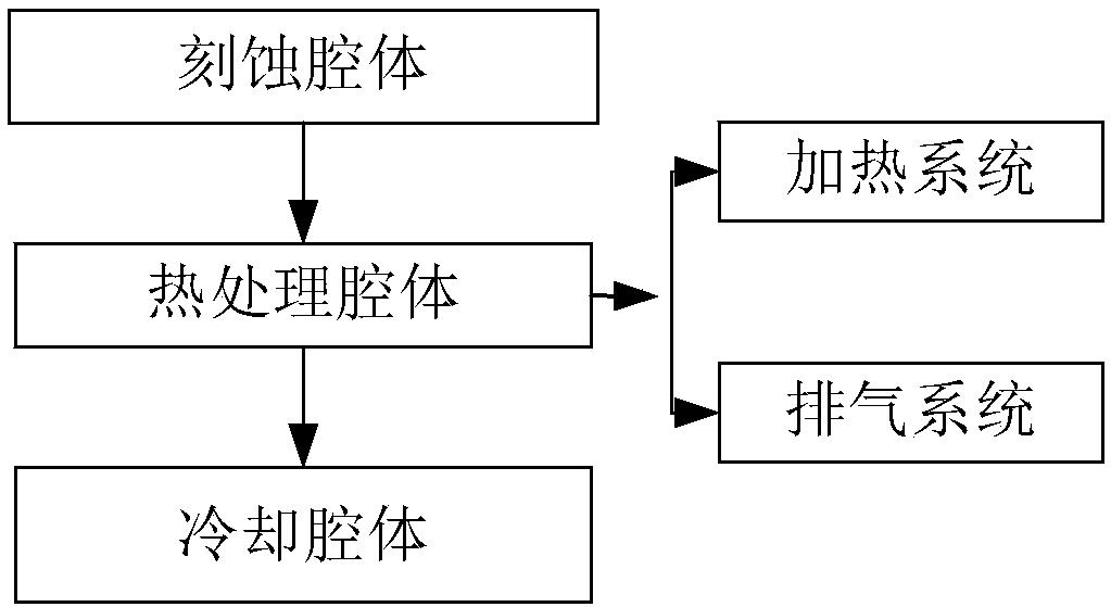
[0036] Such as figure 1 As shown, the present invention provides a wafer etching equipment, which includes:
[0037] An etching cavity, the etching cavity provides an etching gas containing HBr to etch the wafer;
[0038] A heat treatment cavity, the heat treatment cavity includes a heating system and an exhaust system, and the working temperature of the heat treatment cavity is not less than the working temperature of the etching cavity, and the wafer is etched by the etching cavity After etching, enter the heat treatment chamber, and remove HBr remaining on the surface of the wafer through the heating system and exhaust system.
[0039] The present invention uses the heat treatment chamber including the heating system and the exhaust system to remove HBr remaining on the surface of the wafer without cooling the wafer, thereby reducing the corrosion of hydrobromic acid to semiconductor equipment , To extend the life of semiconductor equipment; reduce the generation of HBr condensation on the wafer surface, and improve product quality.
[0040] Specific, such as figure 1 , Shows a structural block diagram of the wafer etching equipment, and the wafer etching equipment mainly includes an etching cavity and a heat treatment cavity. Wherein, the etching chamber is used for dry etching the wafer placed in the etching chamber, the etching gas in the etching chamber mainly includes HBr, and the etching Gas can also include Cl 2 , SF 6 And NF 3 Etc. There is no restriction here. The heat treatment cavity includes the heating system and an exhaust system; through the heating system, a thermal environment is provided for the heat treatment cavity, so that the working temperature of the heat treatment cavity is not less than the working temperature of the etching cavity The temperature is so that the wafer entering the heat treatment chamber will not be cooled during the process of removing HBr remaining on the surface of the wafer, thereby avoiding the generation of HBr condensation. Through the exhaust system, a clean gas that does not react with the wafer and does not contain water molecules is provided to the heat treatment chamber, and the HBr remaining on the surface of the wafer is moved out of the heat treatment chamber through exhaust. Mentioned heat treatment cavity. Therefore, the heat treatment chamber can remove the HBr remaining on the surface of the wafer without condensing with water molecules.
[0041] As a further embodiment of this embodiment, the wafer etching equipment further includes a cooling cavity, and the wafer enters the cooling cavity after being processed by the heat treatment cavity.
[0042] Specifically, in order to further remove HBr remaining on the surface of the wafer, in this embodiment, the wafer etching equipment includes a cooling chamber, and the wafer is transferred to the heat treatment chamber after being processed in the heat treatment chamber. The cooling cavity, wherein the cooling cavity can be a conventional general cooling cavity, and the specific structure and type of the cooling cavity are not limited here. Through the cooling cavity, the residual HBr on the surface of the wafer can be further removed, the probability of defects during the manufacturing process is reduced, and the corrosion damage of the hydrobromic acid to the semiconductor device is reduced.
[0043] As a further embodiment of this embodiment, the range of the working temperature of the heat treatment cavity includes 65°C to 75°C. Since the working temperature of the heat treatment cavity is not less than the working temperature of the etching cavity, The wafer in the heat treatment chamber will not be cooled, thereby reducing the probability of HBr condensation on the surface of the wafer. Preferably, the heat treatment cavity and the etching cavity have the same working temperature, so as to prevent the wafer from being overheated in the heat treatment cavity while ensuring that the wafer is not cooled. Waste of resources and damage to devices on the wafer surface.
[0044] As a further example of this embodiment, the gas in the heat treatment chamber includes one or a combination of nitrogen and inert gas. The specific type of the gas can be selected by a person skilled in the art according to specific needs. Limitation: The gas can provide the heat treatment chamber with a clean gas that does not react with the wafer and does not contain water molecules, so that the HBr remaining on the wafer surface can be exhausted Is removed from the heat treatment chamber.
[0045] As a further example of this embodiment, the heating system includes one or a combination of an electric heating device and a water heating device; the electric heating device may include one or a combination of an electric heating tube and an electric heating rod; The water heating device may include a water heating tube, and the shape of the water heating tube includes one of a figure surrounded by one or a combination of straight lines and curves.
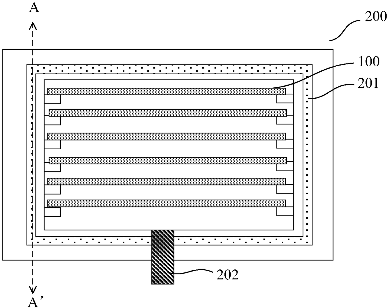
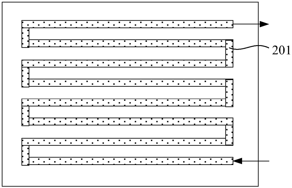
[0046] Specific, such as figure 2 , Shows the structure of the heat treatment cavity. The heat treatment cavity 200 includes an outer wall of the cavity, an inner wall of the cavity, a cavity door (not shown), the heating system, and an exhaust system. The size and material of the outer wall of the cavity, the inner wall of the cavity, and the door of the cavity are not limited here. The movement of the cavity door is preferably a translation in the vertical direction, so as to reduce the equipment space occupied by the heat treatment cavity 200. The heating system includes one or a combination of an electric heating device and a water heating device, wherein the heating device is located between the outer wall of the cavity and the inner wall of the cavity. In this embodiment, the heating device is preferably a water heating device in contact with the outer side of the inner wall of the cavity, and a water heating tube 201 is used to heat the heat treatment cavity 200 in a water circulation manner, so as to save energy. . The arrangement of the water heating tube 201 includes one of the figures enclosed by one or a combination of straight lines and curves, preferably arranged in an S-shape on the outside of the inner wall of the cavity, and the water The water inlet of the heating pipe 201 is located at the bottom of the heat treatment cavity 200, and the water outlet of the water heating pipe 201 is located at the top of the heat treatment cavity 200, so as to make the heat treatment cavity 200 evenly heated and save energy. Such as image 3.
[0047] As a further example of this embodiment, the heating system further includes a temperature program control table (not shown) for setting, displaying, and adjusting the working temperature of the heat treatment cavity 200, so as to improve the heat treatment cavity The convenience of controlling the working temperature of 200 ensures that the working temperature of the heat treatment cavity 200 is not less than the working temperature of the etching cavity. The temperature program control table may be set on the outer wall of the heat treatment chamber 200, or may be directly connected to the operation interface (UI) of the wafer etching equipment, which is not limited here.
[0048] As a further embodiment of this embodiment, the exhaust system further includes a gas storage tank (not shown) and an air control valve (not shown). Wherein, the gas storage tank is connected to an air inlet (not shown) in the inner wall of the cavity through the gas control valve, so as to control the flow of the gas through the gas control valve and reduce the crystal resistance. The damage of the circle 100, under the premise of ensuring that the wafer 100 is not damaged, causes the HBr remaining on the surface of the wafer 100 to pass through the exhaust device connected to the exhaust port 202 in the inner wall of the cavity, Being removed from the heat treatment chamber 200, the exhaust device includes an air pump, and the specific types of the air control valve and the exhaust device in the exhaust system are not limited here. The positions of the air inlet and the air outlet 202 can be selected according to specific manufacturing process requirements, and are not limited here.
[0049] As a further example of this embodiment, the number of wafers 100 contained in the heat treatment chamber 200 ranges from 1 to 30.
[0050] Specifically, in order to reduce damage to the wafer 100, the inner wall of the cavity in the heat treatment chamber 200 preferably has a plurality of sets of horizontal grooves arranged in parallel to carry the wafer 100. Process efficiency and operation convenience. The number of wafers 100 contained in the heat treatment chamber 200 is preferably 25. The staff can also select the number of wafers 100 that can be accommodated according to the requirements of the specific process. There are no restrictions.
[0051] Such as Figure 4 , The present invention also provides a wafer etching method, including the following steps:
[0052] Provide wafers;
[0053] Provide any of the wafer etching equipment;
[0054] Placing the wafer in the etching chamber, and etching the wafer with an etching gas containing HBr;
[0055] The wafer is placed in the heat treatment chamber, and the HBr remaining on the surface of the wafer is removed through the heating system and the exhaust system.
[0056] As a further embodiment of this embodiment, after the wafer is processed by the heat treatment cavity, it further includes a step of entering a cooling cavity. In order to further remove the residual HBr on the surface of the wafer, the probability of defects during the manufacturing process is reduced, and the corrosion damage of the hydrobromic acid to the semiconductor device is reduced.
[0057] Specifically, before the wafer enters the heat treatment chamber, the heating system and the exhaust system are activated to ensure that when the wafer enters the heat treatment chamber, due to the heating system, Therefore, the wafer will not be in a cooling state; and due to the effect of the exhaust system, no water molecules exist in the heat treatment chamber, thereby reducing the generation of HBr condensation on the wafer surface. During the process, the heating system and exhaust system continue to act on the heat treatment chamber to provide continuous working temperature and clean gas for the heat treatment chamber until the end of the process, thereby ensuring that the wafer is in Without cooling, the residual HBr on the surface of the wafer is removed.
[0058] In summary, the wafer etching equipment and wafer etching method of the present invention use a heat treatment chamber including a heating system and an exhaust system to remove HBr remaining on the surface of the wafer without cooling the wafer. Thereby reducing the corrosion of hydrobromic acid to semiconductor equipment, prolonging the life of the semiconductor equipment; reducing the generation of HBr condensation on the wafer surface, and improving product quality. Therefore, the present invention effectively overcomes various shortcomings in the prior art and has high industrial value.
[0059] The above-mentioned embodiments only exemplarily illustrate the principles and effects of the present invention, but are not used to limit the present invention. Anyone familiar with this technology can modify or change the above-mentioned embodiments without departing from the spirit and scope of the present invention. Therefore, all equivalent modifications or changes made by those with ordinary knowledge in the technical field without departing from the spirit and technical ideas disclosed in the present invention should still be covered by the claims of the present invention.

PUM

no PUM

Description & Claims & Application Information

We can also present the details of the Description, Claims and Application information to help users get a comprehensive understanding of the technical details of the patent, such as background art, summary of invention, brief description of drawings, description of embodiments, and other original content. On the other hand, users can also determine the specific scope of protection of the technology through the list of claims; as well as understand the changes in the life cycle of the technology with the presentation of the patent timeline. Login to view more.

Similar technology patents

Thick film photoresist detergent

InactiveCN101738880Aless corrosivereduce corrosion
Owner:ANJI MICROELECTRONICS (SHANGHAI) CO LTD

Synthesis method of polyamide polyamine resin

Owner:佛山市帕里达新材料科技有限公司

Classification and recommendation of technical efficacy words

  • reduce corrosion
  • extend your life

Method for controlling uniform heating of switch device of switch power source

InactiveCN104600998AUniform heatingextend your life
Owner:SICHUAN INJET ELECTRIC CO LTD +1

Light-emitting element

ActiveCN103081155AImprove quantum efficiencyextend your life
Owner:SEMICON ENERGY LAB CO LTD

Method, system and device for controlling vehicle power device and storage medium

ActiveCN108394401AAvoid violent dynamic load changesextend your life
Owner:TSINGHUA UNIV

Packaging method for white light illuminating diode

InactiveCN101068034AReduce light decay rateextend your life
Owner:NINGBO ANDY OPTOELECTRONIC CO LTD
Why Eureka
Try Eureka