Sludge gasifier

A sludge gasification and sludge technology, which is applied in the gasification process, the manufacture of combustible gas, the petroleum industry, etc., can solve the problems of easy leakage, low gas conversion efficiency, low recovery rate, etc., and achieves reduction in volume and filling. The effect of burying space and improving recycling efficiency

Pending Publication Date: 2019-03-19
上海迪琰环保科技有限公司
View PDF0 Cites 0 Cited by
  • Summary
  • Abstract
  • Description
  • Claims
  • Application Information

AI Technical Summary

Problems solved by technology

[0005] The technical problem to be solved by the present invention is to provide a sludge gasification furnace, which can solve the problems of low gas conversion efficiency, low recovery rate and easy leakage in the sludge gasification furnace in the prior art

Method used


Image

  • Sludge gasifier

Examples


Embodiment Construction

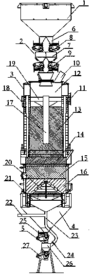
[0034] Such as figure 1 As shown, a sludge gasification furnace includes a sludge storage bin 1, a feeding mechanism 2, a furnace body 3, a closed ash bin 4 and a slagging mechanism 5, a sludge storage bin 1, a feeding mechanism 2, The furnace body 3, the closed ash bin 4 and the slag discharge mechanism 5 are arranged in sequence from top to bottom. The number of feeding mechanisms 2 is two, which are arranged side by side between the sludge storage bin 1 and the furnace body 3 . The feeding mechanism 2 includes a feeding buffer bin 7, which is respectively connected to the sludge storage bin 1 and the furnace body 3 through the feeding pipeline 6, and a The first rotary feed valve 8 and the second rotary feed valve 9 are arranged between the feed buffer bin 7 and the furnace body 3 . The feeding process of this embodiment is as follows. The sludge particles are stored in the sludge storage bin 1. When feeding, first open the first rotary feed valve 8, close the second rota...


PUM


Abstract

The invention discloses a sludge gasifier, comprising a sludge storage bin, a feeding mechanism, a body, a sealed ash bin and a residue discharge mechanism which are connected sequentially from top tobottom. The feeding mechanism includes a feeding buffer bin; the feeding buffer bin is connected with the sludge storage bin and the body through feed pipes; a first rotary feed valve is arranged between the feeding buffer bin and the sludge storage bin; a second rotary feed valve is arranged between the feeding buffer bin and the body. The feeding mechanism is arranged between the sludge storagebin and the body and helps prevents fuel gas in the body from leaking out of a feed port during sludge feeding; fuel gas recycling efficiency is improved, and it is ensured that the whole sludge gasifier runs safely and stably.

Description

technical field [0001] The invention relates to the technical field of sludge comprehensive utilization, in particular to a sludge gasifier. Background technique [0002] At present, domestic sludge is mainly treated by mechanical dehydration, thermal drying, aerobic fermentation, anaerobic digestion, and dry incineration. According to the statistics of national sludge harmless treatment and disposal data, in the current sludge harmless treatment projects, the proportion of dry treatment still ranks first, and the proportion of mechanical deep dehydration is higher than that of energy dry treatment. Compare. Under the guidance of the policy, most sludge dewatering and drying projects adopt the disposal route of mechanical dehydration and landfill. On the other hand, the sludge treatment and disposal costs in the BOT price of most sewage treatment plants are calculated according to the landfill method. Considering the maximization of cost-effectiveness, deep dewatering la...

Claims


Application Information

Patent Timeline
Patent Type & Authority Applications(China)
IPC IPC(8): C10J3/20C10J3/66
CPCC10J3/20C10J3/66C10J2300/0926C10J2300/0956
Inventor 高志王弘杨乐于高鹏
Owner 上海迪琰环保科技有限公司
Why Eureka
Try Eureka