Glass spin-drying device

A glass and spin-drying disk technology, which is applied in the direction of drying gas arrangement, drying, dryer, etc., can solve the problems of long time for drying glass, easy wiping marks on the glass, and affecting the appearance of the product, so as to facilitate concentration Collect and process, improve stability, and improve efficiency

Pending Publication Date: 2019-03-19
成都市澳格斯科技有限公司
View PDF5 Cites 3 Cited by
  • Summary
  • Abstract
  • Description
  • Claims
  • Application Information

AI Technical Summary

Problems solved by technology

[0002] At present, the glass needs to be cleaned after etching. After cleaning, the water droplets on the glass surface should be removed. Generally, drying or manual wiping is used to remove the water droplets. It takes a long time to dry the glass. Dust is sticky, and dust removal treatment is required in the follow-up; manual wiping is easy to cause damage to the glass during the treatment process, and the wiped glass is prone to wiping marks, which affects the appearance of the product

Method used


Image

  • Glass spin-drying device
  • Glass spin-drying device
  • Glass spin-drying device

Examples


Embodiment 1

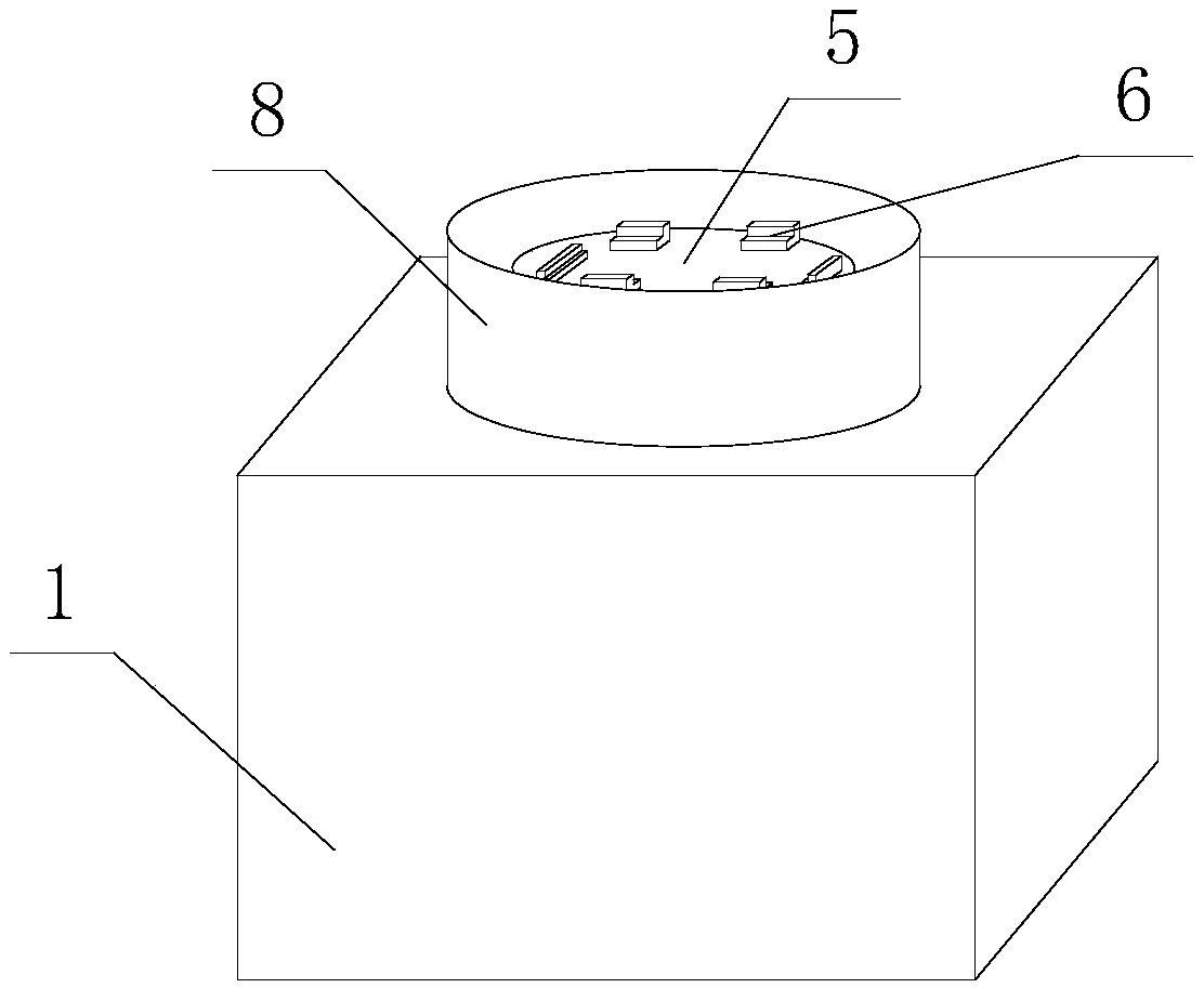
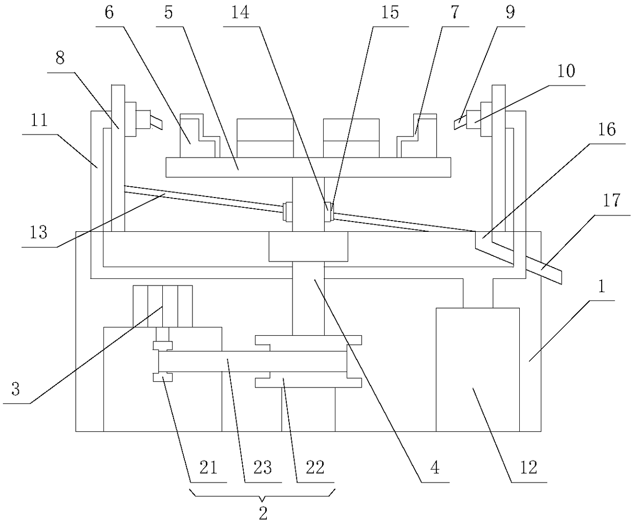
[0029] Such as figure 1 , figure 2 and image 3 As shown, the glass drying device provided in this embodiment includes a workbench 1, which is a hollow box inside, and the workbench 1 is provided with a driving wheel 21, a driven wheel 22, a belt 23 and a driving motor 3, The output shaft of the drive motor 3 is connected with one end of the driving wheel 21, the driving wheel 21 is connected with the driven wheel 22 through the belt 23, the bottom end of the driven wheel 22 is connected with the inner bottom surface of the workbench 1 through the support shaft, and the top is connected with the rotating shaft 4 One end of the rotating shaft 4 is connected to one end of the driven wheel 22 and stretches out from the surface of the workbench 1 and is connected with a drying disc 5. The center of the bottom surface of the drying disc 5 is connected with the top of the rotating shaft 4, and the surface of the drying disc 5 is surrounded by There are several clamping platforms ...

Embodiment 2

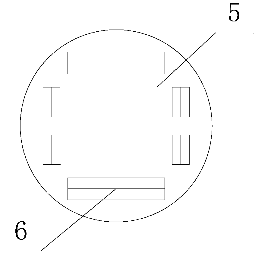
[0031] The glass drying device provided in this embodiment includes a workbench 1, which is a hollow box inside, and a driving wheel 21, a driven wheel 22, a belt 23 and a drive motor 3 are arranged in the workbench 1, and the drive The output shaft of the motor 3 is connected to one end of the driving wheel 21, the driving wheel 21 is connected to the driven wheel 22 through the belt 23, the bottom end of the driven wheel 22 is connected to the inner bottom surface of the workbench 1 through the support shaft, and the top is connected to one end of the rotating shaft 4 , the end of the rotating shaft 4 away from the driven wheel 22 protrudes from the surface of the workbench 1 and is connected with a drying disc 5, the center of the bottom surface of the drying disc 5 is connected with the top of the rotating shaft 4, and the surface of the drying disc 5 is rectangularly distributed around There are several card placement platforms 6, the card placement platform 6 is stepped, ...

Embodiment 3

[0033] The glass drying device provided in this embodiment includes a workbench 1, which is a hollow box inside, and a driving wheel 21, a driven wheel 22, a belt 23 and a drive motor 3 are arranged in the workbench 1, and the drive The output shaft of the motor 3 is connected to one end of the driving wheel 21, the driving wheel 21 is connected to the driven wheel 22 through the belt 23, the bottom end of the driven wheel 22 is connected to the inner bottom surface of the workbench 1 through the support shaft, and the top is connected to one end of the rotating shaft 4 , the end of the rotating shaft 4 away from the driven wheel 22 protrudes from the surface of the workbench 1 and is connected with a drying disc 5, the center of the bottom surface of the drying disc 5 is connected with the top of the rotating shaft 4, and the surface of the drying disc 5 is rectangularly distributed around There are several card placement platforms 6, the card placement platform 6 is stepped, ...


PUM


Abstract

The invention discloses a glass spin-drying device which comprises a workbench; a transmission mechanism is installed below the workbench; a drive motor is connected to the input end of the transmission mechanism, and a rotary shaft is connected to the output end of the transmission mechanism; one end, far away from the transmission mechanism, of the rotary shaft extends out of the surface of theworkbench; a spin-drying disc is connected to the end, far away from the transmission mechanism, of the rotary shaft; multiple clamping placement tables are distributed at the periphery of the surfaceof the spin-drying disc in a rectangular shape; the clamping placement tables distributed on the two opposite sides of a rectangle are symmetrically arranged two by two; a rectangular region enclosedby multiple clamping placement tables is matched with a glass sheet to be dried in size; each clamping placement table is in a ladder shape; a ladder of each clamping placement table is arranged awayfrom the edge of the spin-drying disc; and the external of each clamping placement table is wrapped with an antiskid damping layer. The glass spin-drying device provided by the invention is reasonable in design, can effectively improve the efficiency of removing water drops on the glass sheet, can ensure the glass sheet not to be damaged at the same time and has certain dust removal effect.

Description

technical field [0001] The invention belongs to the technical field of glass production and processing, and in particular relates to a glass drying device. Background technique [0002] At present, the glass needs to be cleaned after etching. After cleaning, the water droplets on the glass surface should be removed. Generally, drying or manual wiping is used to remove the water droplets. It takes a long time to dry the glass. Dust is attached, and subsequent dust removal treatment is required; manual wiping can easily damage the glass during the treatment process, and the wiped glass is prone to wiping marks, which affects the appearance of the product. Contents of the invention [0003] The technical problem to be solved by the present invention is to provide a glass drying device for the above-mentioned deficiencies in the prior art, which can quickly remove water droplets and water stains remaining on the glass surface after cleaning, thereby improving work efficiency a...

Claims


Application Information

Patent Timeline
Patent Type & Authority Applications(China)
IPC IPC(8): F26B11/18F26B5/08F26B25/02F26B25/18F26B25/00F26B21/00
CPCF26B5/08F26B11/18F26B21/004F26B25/00F26B25/02F26B25/18
Inventor 李和平黄春霞
Owner 成都市澳格斯科技有限公司
Why Eureka
Try Eureka