Lens defect detection device

A defect detection and lens technology, used in measuring devices, material analysis by optical means, instruments, etc., can solve problems such as difficulty in guaranteeing stability and reliability, inability to quantify lens defects, and inability to strictly match production speeds, etc. Achieve the effect of reducing labor intensity and enterprise production cost, good practicability and scalability, and reducing labor intensity

Inactive Publication Date: 2019-03-19
沈峥
View PDF0 Cites 7 Cited by
  • Summary
  • Abstract
  • Description
  • Claims
  • Application Information

AI Technical Summary

Problems solved by technology

The following main problems exist in the current manual detection: 1. Low detection accuracy: The detection results will be affected by many factors such as workers’ physiological differences, experience, emotion and fatigue, and the stability and reliability are difficult to guarantee; 2. The judgment standard is vague: It is impossible to quantify and judge lens defects, which eventually leads to uneven product quality; 3. Slow detection speed: the detection speed of skilled workers is about 6 pieces per minute, which cannot strictly match the production speed on the assembly line, which affects production efficiency; 4. High labor intensity: workers need to be in a very focused working state and a bright working environment for a long time, which is easy to damage vision; Above 5.0, the training period for workers usually takes 1 month to get on the job. After working for one year, due to vision loss, new employees need to be recruited again, which increases production costs

Method used


Image

  • Lens defect detection device
  • Lens defect detection device
  • Lens defect detection device

Examples


Embodiment Construction

[0023] The embodiments involved in the present invention will be described in further detail below in conjunction with the accompanying drawings.

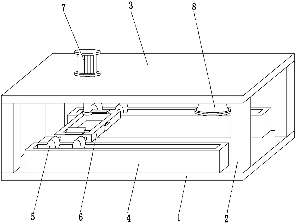
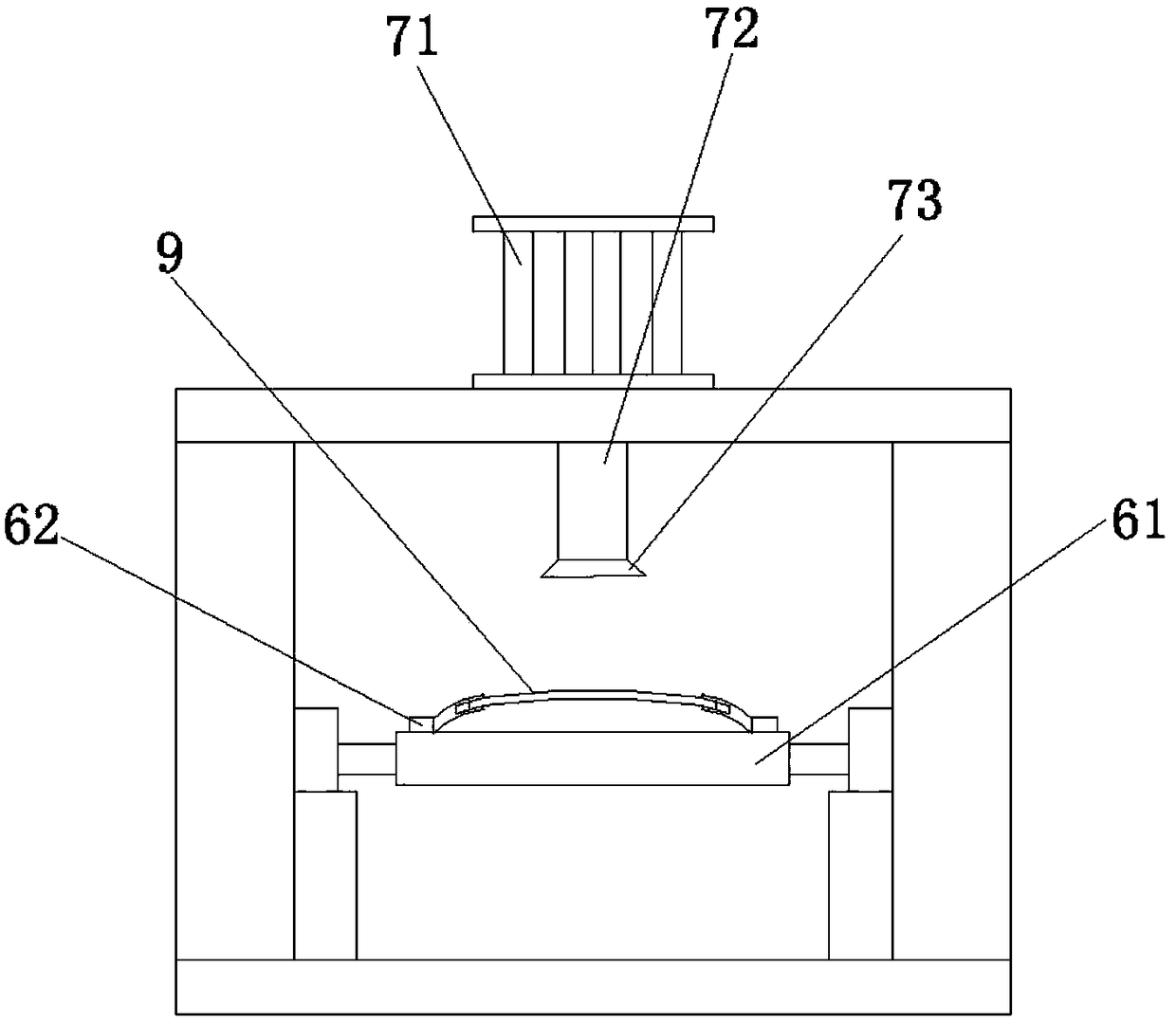
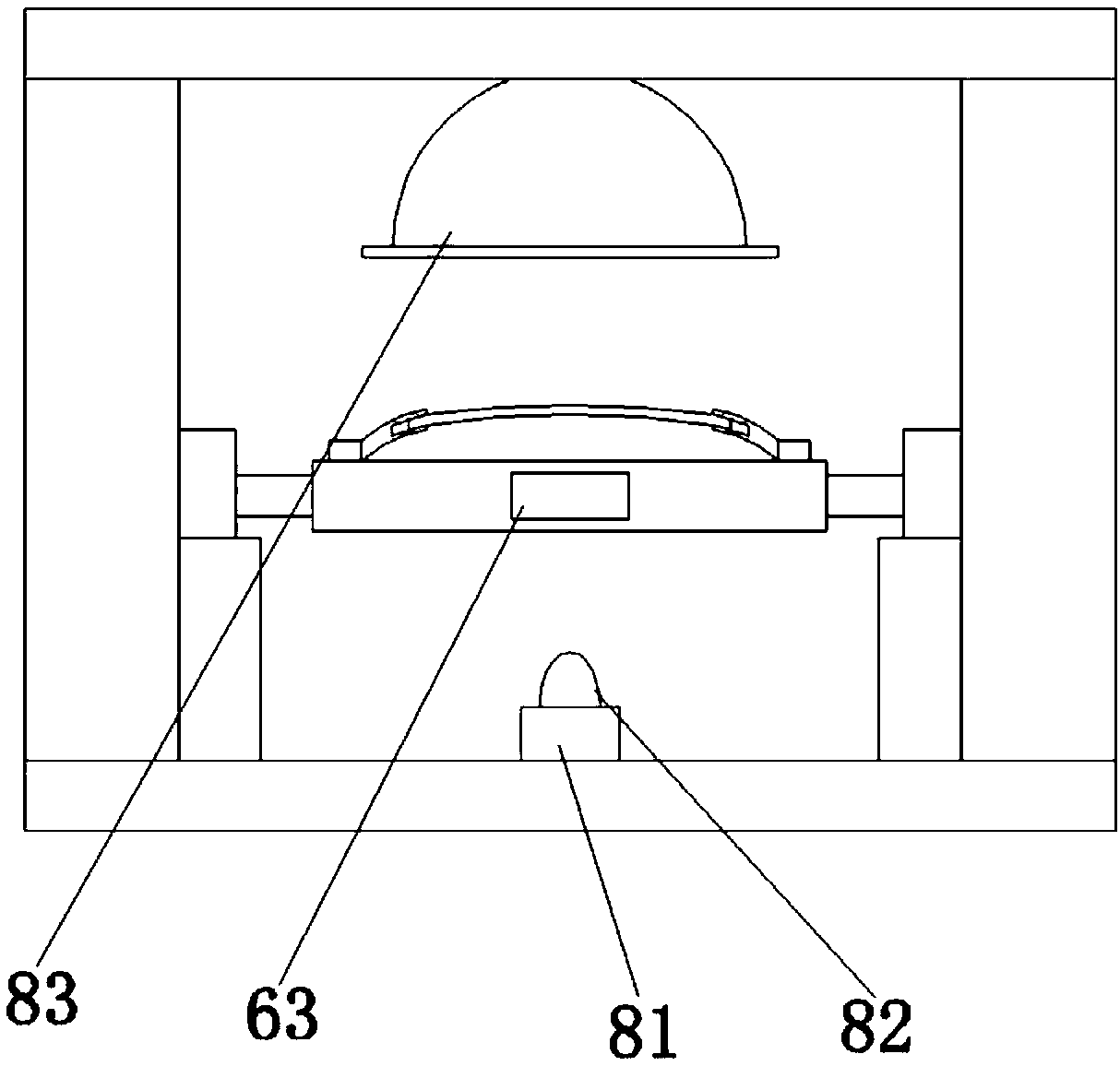
[0024] combine figure 1 , a lens defect detection device, including a device body, the device body is connected to an external PLC industrial computer for communication, the device body includes a base 1, a top plate 3, and a support column 2 arranged between the base 1 and the top plate 3, the base 1 The upper surface is provided with a pair of slide rails 4 along the long side direction, above the slide rails 4 is provided with a moving mechanism 5, the moving mechanism 5 is connected with the bearing plate 6, and the moving mechanism 5 is arranged on the outside of the bearing plate 6 along the slide rail 4 direction, One end of the top plate 3 is provided with a pneumatic dust blowing mechanism 7, and the other end of the top plate 3 is provided with an optical detection mechanism 8. Both the pneumatic dust blowing mechanism 7 ...


PUM


Abstract

The invention provides a lens defect detection device which comprises a device body, wherein the device body is in communication connection with an external PLC (Programmable Logic Controller) industrial personal computer; the device body comprises a base, a top plate and supporting columns arranged between the base and the top plate; a pair of sliding rails is arranged on the upper surface of thebase along a long side direction; a moving mechanism is arranged on the sliding rails and connected with a bearing plate; the moving mechanism is arranged on the outer side of the bearing plate alongthe direction of the sliding rails; a pneumatic dust blowing mechanism is arranged at one end of the top plate; an optical detection mechanism is arranged at the other end of the top plate; and the pneumatic dust blowing mechanism and the optical detection mechanism are positioned on a central axis of the top plate along the long side direction. The device disclosed by the invention is capable ofeffectively replacing manual labor to detect lens defects and has unified quantized criterion, the product quality consistency is ensured, the detection accuracy is high, the stability and reliability are excellent, the detection speed is high, and the production efficiency is improved.

Description

technical field [0001] The invention relates to the technical field of industrial detection equipment, in particular to a lens defect detection device. Background technique [0002] Optical glass lenses are generally made of high-purity silicon, boron, sodium, potassium, zinc, lead, magnesium, calcium, barium and other oxides mixed according to a specific formula, melted in a platinum crucible at high temperature, stirred evenly with ultrasonic waves to remove air bubbles, and then subjected to long-term The temperature is lowered slowly over time to avoid internal stress in the glass block. The cooled glass block must be measured by optical instruments to check whether the purity, transparency, uniformity, refractive index and dispersion rate meet the specifications. The qualified glass block is heated and forged to form an optical lens blank. [0003] For the detection of lens defects, it is basically still in the stage of manually placing the lens under a high-brightness...

Claims


Application Information

Patent Timeline
Patent Type & Authority Applications(China)
IPC IPC(8): G01N21/958
CPCG01N21/958
Inventor 沈峥
Owner 沈峥
Why Eureka
Try Eureka