Efficient low-profile wide-axis ratio bandwidth large-scale circularly-polarized array antenna

A technology with axial ratio bandwidth and low profile is applied in the field of antenna arrays to achieve the effects of simple manufacture, low profile and low cost

Inactive Publication Date: 2019-03-19
XIANGNAN UNIV +2
View PDF4 Cites 25 Cited by
  • Summary
  • Abstract
  • Description
  • Claims
  • Application Information

AI Technical Summary

Problems solved by technology

[0005] The purpose of the present invention is to overcome the shortcomings and deficiencies of the existing planar circularly polarized antenna array, and provide a large-scale circularly polarized array antenna with high efficiency, low profile, wide axis ratio and bandwidth

Method used


Image

  • Efficient low-profile wide-axis ratio bandwidth large-scale circularly-polarized array antenna
  • Efficient low-profile wide-axis ratio bandwidth large-scale circularly-polarized array antenna
  • Efficient low-profile wide-axis ratio bandwidth large-scale circularly-polarized array antenna

Examples


Embodiment 1

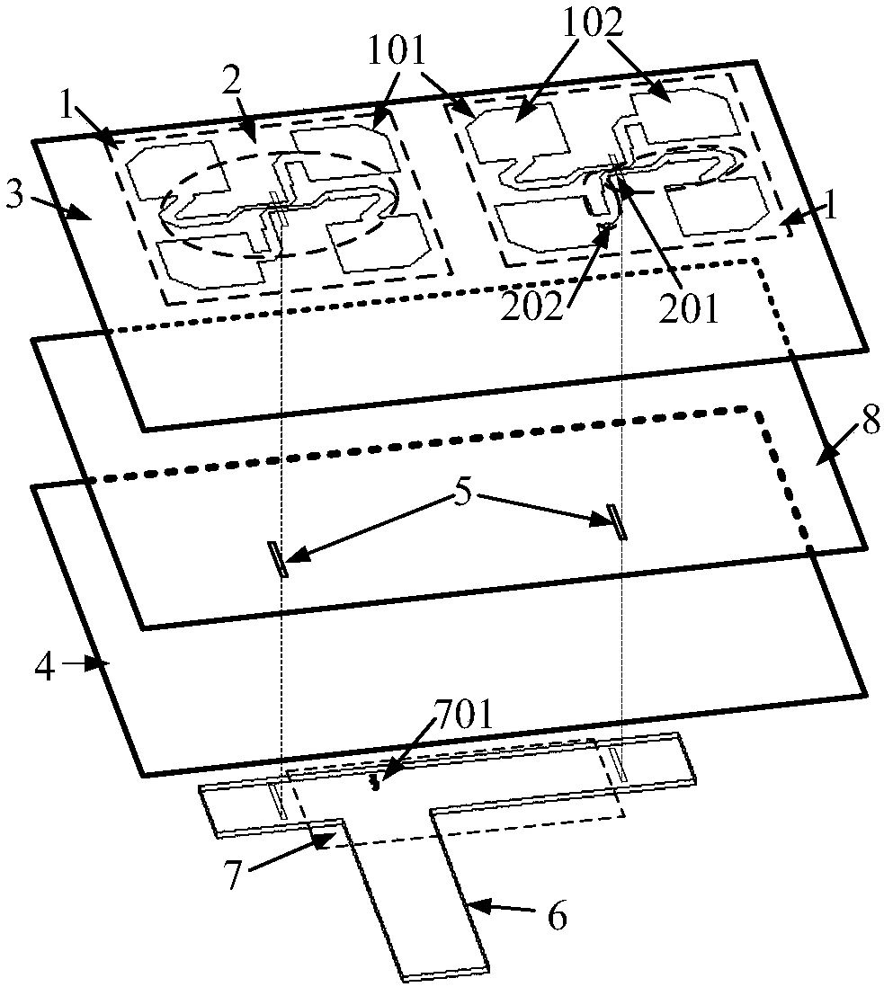
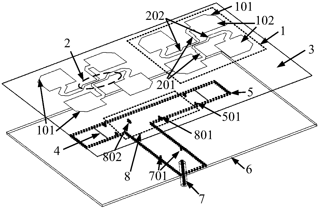
[0031] The 2×4 wide-axis ratio bandwidth planar circularly polarized antenna array of this embodiment is as follows figure 2 As shown, the radiation patch-102 with cut corners-101 and the sequentially rotating microstrip feed network-2 are printed on the film-3, and every four rectangular radiation patches-102 with cut corners and a sequentially rotated microstrip feed network -2 constitutes a circular polarized sub-array-1; the SIW feed network-5 is constructed on the dielectric board-6 with the short-circuit via-501 array using traditional PCB technology, and the circle is excited through the rectangular slot-4 etched on the SIW Polarization sub-array-1; SIW equal-amplitude anti-phase power divider-8 excites two circular polarimetric sub-arrays to ensure equal-amplitude and in-phase excitation of 2×4 radiating patches. The via-501 adjusts the matching characteristics of the circularly polarized subarray-1, and the vias-801 and 802 adjust the matching characteristics and pow...

Embodiment 2

[0034] The 6×16 wide-axis ratio bandwidth planar circularly polarized antenna array of this embodiment is as follows Figure 7 As shown, 6×16 radiating patches-102 with cut corners-101 and 3×8 microstrip feeding networks-2 are printed on the film-3, and every four radiating patches are rotated by 90º in sequence, and one The microstrip feed network-2 constitutes a circularly polarized sub-array-1. The SIW feed network-5 is constructed on the dielectric board-6 by using the traditional PCB process with the array of short-circuit vias-501, and the circularly polarized sub-array-1 is excited through the rectangular slit-4 etched on the SIW; every two sub-arrays- 1 Use a SIW equal-amplitude inverting power divider-8 excitation to ensure equal-amplitude and in-phase excitation for 2×4 radiating patches. It is further expanded through the SIW equal-amplitude equal-phase power divider-9 and the one-to-two equal-phase power divider-10, and finally feeds the entire antenna array throu...


PUM


Abstract

The invention relates to an efficient low-profile wide-axis ratio bandwidth large-scale circularly-polarized array antenna, in particular to a circularly-polarized array antenna composed of a metal floor with a coupling gap, a thin film printed with radiation patches and sequential rotating microstrip feed networks, a main feed network and a foam or hollow dielectric plate for supporting the thinfilm. Each four sequentially and rotarily-placed corner cut radiation metal patches and one sequential rotating microstrip feed network together form a sub array, coupling with the main feed network through the gap on the metal floor is carried out, sequential 90 DEG-difference equal-amplitude excitation of each sub array element is carried out, and thus, wide-axis ratio bandwidth circularly-polarized radiation is realized. Through increasing the stage number of the power divider and the number of sub arrays of the main feed network, a large-scale circularly-polarized array antenna can be constructed. In comparison with the existing circularly-polarized array antenna technology, the efficient low-profile wide-axis ratio bandwidth large-scale circularly-polarized array antenna has the advantages of wide axis ratio bandwidth, simple structure, high radiation efficiency, low profile, light weight, low cost and easy expansion to a large-scale array, and is especially suitable for mobile terminals and satellite terminals.

Description

technical field [0001] The invention relates to an antenna array in the technical fields of mobile communication, satellite communication and microwave communication, and more specifically relates to an efficient planar circularly polarized antenna array. Background technique [0002] High-gain circularly polarized antenna arrays are widely used in mobile communications and satellite communications, which can avoid polarization mismatch between transceiver antennas and achieve high-speed, stable and reliable communications. For mobile satellite terminals, such as vehicles, ships, aircraft, etc., due to the continuous movement of the terminal, not only requires high antenna gain, but also has a lot of restrictions on the weight and profile of the antenna. Early satellite receiving terminals used reflector antennas controlled by servo mechanisms. Although wide-bandwidth circular polarization or even dual circular polarization radiation characteristics can be obtained, the prof...

Claims


Application Information

Patent Timeline
Patent Type & Authority Applications(China)
IPC IPC(8): H01Q1/38H01Q1/48H01Q1/52H01Q21/06
CPCH01Q1/38H01Q1/48H01Q1/52H01Q21/061
Inventor 黄健全邱枫唐政华蒋纯志雷大军金桂姚敏
Owner XIANGNAN UNIV
Why Eureka
Try Eureka