Spin riveting machine

A technology of riveting machine and frame, which is applied in the field of machinery to achieve the effects of improving connection firmness, avoiding impact and wide applicability

Pending Publication Date: 2019-03-22
TAIZHOU HONGXIN CRANKSHAFT
View PDF1 Cites 6 Cited by
  • Summary
  • Abstract
  • Description
  • Claims
  • Application Information

AI Technical Summary

Problems solved by technology

[0004] The purpose of the present invention is to solve the above problems in the prior art, and propose a riveting machine. The technical problem to be solved is how to improve the firmness of the connection between the crankshaft and the oil flinger

Method used


Image

  • Spin riveting machine
  • Spin riveting machine
  • Spin riveting machine

Examples


Embodiment Construction

[0035] The following are specific embodiments of the present invention and in conjunction with the accompanying drawings, the technical solutions of the present invention are further described, but the present invention is not limited to these embodiments.

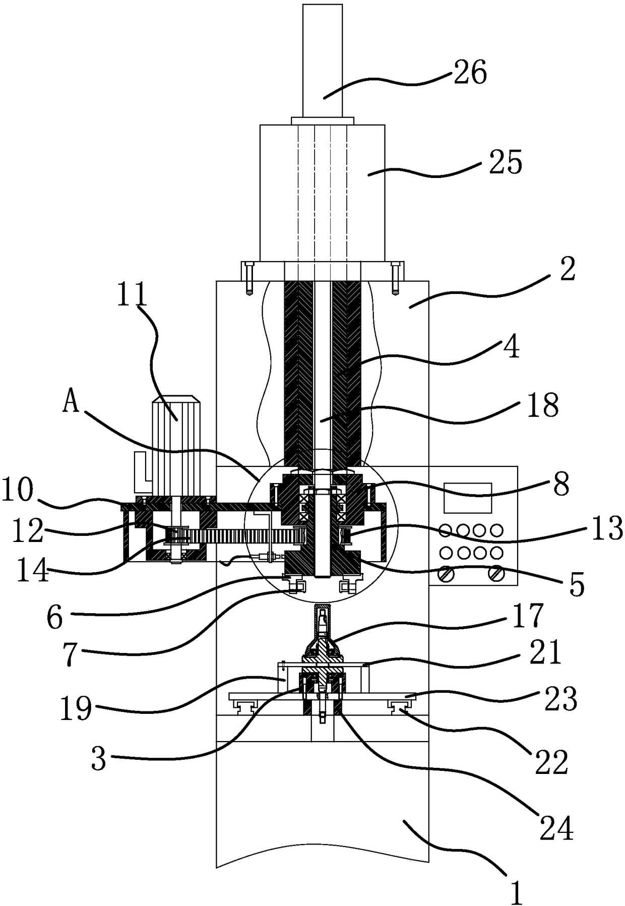
[0036] Such as figure 1 and figure 2 As shown, a riveting machine includes a frame 1, a headstock 2 is arranged on the frame 1, a main shaft 4 capable of moving up and down is arranged in the headstock 2, a hydraulic cylinder 25 is fixed on the upper end of the headstock 2, and the hydraulic cylinder 25 The output shaft of the main shaft is fixed to the main shaft 4, the lower end of the main shaft 4 extends outside the main shaft box 2, and the lower end of the main shaft 4 is connected with a rotatable rotary head 5.

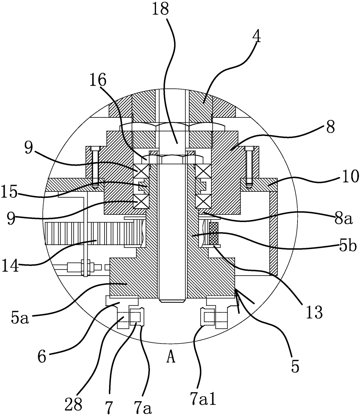
[0037] Such as figure 1 and figure 2 As shown, specifically, the lower end of the main shaft 4 is externally threaded with a coupling sleeve 8. The rotary head 5 includes a head 5a and a rod 5b fixed ...


PUM


Abstract

The invention provides a spin riveting machine, and belongs to the technical field of machinery. The problem that the connection between an existing oil thrower and crankshaft is not firm enough is solved. The spin riveting machine comprises a machine frame, a mounting block and a spindle box, wherein the mounting block and the spindle box are arranged on the machine frame. The mounting block is provided with a mounting hole arranged in the vertical direction in a penetrating mode. The spindle box is internally provided with a spindle capable of moving up and down, and the lower end of the spindle extends outside the spindle box. A rotating head which can rotate is connected to the lower end of the spindle, and two positioning blocks are arranged at the lower end of the rotating head. Theinner sides of the two positioning blocks are separately connected with pressing wheels which can rotate, annular convex portions are arranged on the outer peripheral surfaces of the two pressing wheels, when the rotating head rotates, the movement trajectories of the two annular convex portions coincide, and extrusion faces inclined towards the outer sides of the positioning blocks are arranged on the inner sides of the two annular convex portions. The spin riveting machine has the advantages of high precision of spin riveting, simple operation, good connection fastness between the crankshaftand the oil thrower after riveting and the like.

Description

technical field [0001] The invention belongs to the technical field of machinery and relates to a riveting machine. Background technique [0002] The crankshaft is the most important part of the engine. It bears the force transmitted by the connecting rod and converts it into torque, which is output through the crankshaft and drives other accessories on the engine to work. At present, the crankshaft is composed of two cranks and a crank pin connected between the two cranks. The connecting rod is sleeved on the crank pin and a connecting rod bearing is arranged between the connecting rod and the crank pin. , the two cranks include the shaft and the connecting block fixedly connected with the shaft, and in order to smoothly lubricate the connecting rod, an oil channel is generally processed on one of the shafts to facilitate the oil from the crankcase through the oil The oil passage is introduced into the crankshaft, and the oil passage is introduced into the crankpin, and fi...

Claims


Application Information

Patent Timeline
Patent Type & Authority Applications(China)
IPC IPC(8): B21D39/00
CPCB21D39/00
Inventor 李红兵
Owner TAIZHOU HONGXIN CRANKSHAFT
Why Eureka
Try Eureka