Sponge cutting machine

A technology of sponge cutting machine and cutting mechanism, applied in metal processing and other directions, can solve the problems of uneven incision, small application range and low cutting efficiency, and achieve the effect of neat incision, good cutting effect and speeding up cutting efficiency.

Inactive Publication Date: 2019-03-22
四川雷恩新材料有限公司
View PDF0 Cites 3 Cited by
  • Summary
  • Abstract
  • Description
  • Claims
  • Application Information

AI Technical Summary

Problems solved by technology

[0005] The object of the present invention is: in order to solve the problems that the existing sponge cutting machine has a small application range, uneven incisions and low cutting efficiency, the present invention provides a sponge cutting machine

Method used


Image

  • Sponge cutting machine

Examples


Embodiment 1

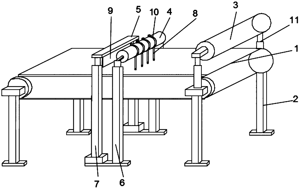
[0026] Such as figure 1 As shown, this embodiment provides a sponge cutting machine, including a conveyor belt 1, the bottom of the conveyor belt 1 is provided with a support column 2, and the top of the conveyor belt 1 is sequentially provided with an extrusion mechanism 3, a first cutting mechanism and The second cutting mechanism, the extruding mechanism 3 is supported on the support column 2, the first cutting mechanism includes a horizontally arranged first installation rod 4, and the second cutting mechanism includes a horizontally arranged second installation rod 5, The first installation rod 4 is installed on the ground through the installation bracket 6, and the second installation rod 5 is installed on the ground through the lifting bracket 7. The length direction of the first installation rod 4 and the second installation rod 5 is arranged perpendicular to the direction of motion of the conveyor belt 1. The bottom of the installation rod 4 is provided with a plurali...

Embodiment 2

[0030] Such as figure 1 As shown, this embodiment is further optimized on the basis of Embodiment 1. Specifically, the first installation rod 4 is cylindrical, the first cutter 8 is installed on the first installation rod 4 through a clamp 10, and the first installation rod 4 is set. The cutter 8 is connected to the first installation rod 4 through the clamp 10 and the width of the first installation rod 4 is larger than the width of the conveyor belt 1. The distance between the cutters can be changed through the elastic clamp 10. The part of the first installation rod 4 beyond the conveyor belt 1 It is used to store the redundant first cutter 8, which is convenient for adjusting the width of the cut out sponge pad, so that the sponge cutting machine of the invention can be used in a wider range.

[0031] As a preferred manner, the width of the first installation rod 4 is greater than the width of the conveyor belt 1. Specifically, the first cutter 8 and the second cutter 9 ar...

Embodiment 3

[0034] Such as figure 1 As shown, this embodiment is further optimized on the basis of embodiment 2. Specifically, the extrusion mechanism 3 includes a roller arranged parallel to the first installation rod 4, and the two ends of the roller are supported by a vertically arranged telescopic mechanism 11. On the support column 2, when the telescopic mechanism 11 is extended, the distance between the lower end of the roller and the conveyor belt 1 is greater than the thickness of the sponge; Thickness, set the roller to facilitate the sponge to be squeezed through the roller.

[0035] As a preferred manner, the lifting support 7 includes screw lifts vertically arranged on both sides of the conveyor belt 1 in the width direction, and the screw lifts are controlled by servo motors, which are easy to control and have high precision.


PUM


Abstract

The invention discloses a sponge cutting machine, and relates to the technical field of sponge cutting equipment. The sponge cutting machine comprises a conveyor belt, supporting columns are arrangedat the bottom of the conveyor belt, and a pressing mechanism, a first cutting mechanism and a second cutting mechanism are sequentially arranged above the conveyor belt from right to left, wherein thefirst cutting mechanism comprises a first mounting rod horizontally arranged, the second cutting mechanism comprises a second mounting rod horizontally arranged, the second mounting rod is mounted onthe ground through a lifting support, the length direction of the first mounting rod and the length direction of the second mounting rod are perpendicular to the movement direction of the conveyor belt, first cutters are arranged at the bottom of the first mounting rod at intervals, a second cutter is arranged at the bottom of the second mounting rod, and the width of the second cutter is largerthan the width of the conveyor belt. According to the sponge cutting machine, the variable-pitch lateral cutters are arranged so that the sponges with different widths can be cut out; the longitudinalcutter is arranged so that the sponges with different lengths can be cut out; and the sponges can be cut out according to different sizes, so that the sponge cutting machine has the wide applicationrange and high cutting efficiency.

Description

technical field [0001] The present invention relates to the technical field of sponge cutting equipment, in particular to a sponge cutting machine. Background technique [0002] Sponge is a kind of polyurethane foam, which belongs to soft polyurethane foam. Because of the porous honeycomb structure, it has excellent softness, elasticity, water absorption and water resistance, and is widely used in sofas, mattresses, clothing, flexible packaging and other industries. [0003] The processing process of the sponge is roughly as follows: After the raw materials are mixed evenly, they enter the oven for foaming and molding. The formed materials are cut by a cutting machine, and then the materials are transported and collected. The existing sponge cutting process generally uses a shaped cutter to cut the end, which is not suitable for cutting sponges of different sizes, and often due to uneven incisions, the sponge needs to be processed again, and when a smaller sponge is require...

Claims


Application Information

Patent Timeline
IPC IPC(8): B26F3/12B26D7/26B26D7/08B26D11/00
CPCB26F3/12B26D7/08B26D7/2614B26D7/2628B26D11/00B26D2011/005
Inventor 邱勇
Owner 四川雷恩新材料有限公司
Why Eureka
Try Eureka