Method and system for determining limit of permeability of unfilled caverns in fractured-vuggy reservoirs
A permeability, fracture-cavity technology, applied in the field of geological exploration, can solve the problems of inability to meet the application requirements of the mine, slow operation speed, limited scale, etc. Effect
- Summary
- Abstract
- Description
- Claims
- Application Information
AI Technical Summary
Problems solved by technology
Method used
Image

Examples
Embodiment approach 1
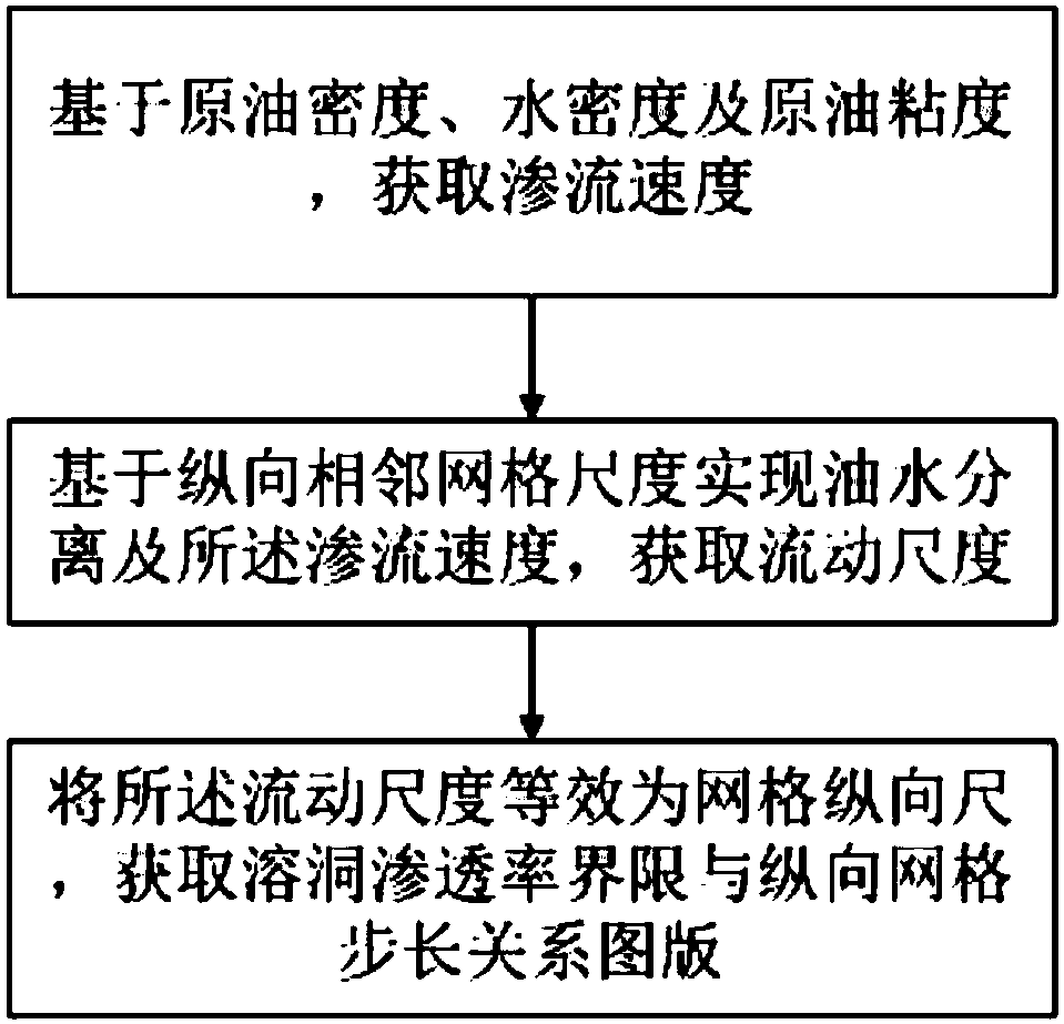
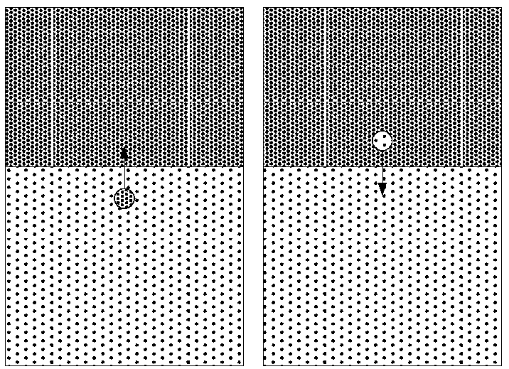
[0032] figure 1 A flow chart of a method for determining the permeability limit of unfilled caves in a fractured-cavity reservoir according to an embodiment of the present invention is shown. figure 2 A schematic diagram of rapid separation of oil phase and water phase according to one embodiment of the present invention is shown. image 3 The relationship curve of seepage velocity and reservoir permeability according to one embodiment of the present invention is shown. Figure 4 It shows a graph of pseudo-permeability values of unfilled caves according to an embodiment of the present invention.
[0033] Such as Figure 1-Figure 4 As shown, in this embodiment, the method for determining the permeability limit of an unfilled cave in a fractured-cavity reservoir according to the present invention includes: obtaining the seepage velocity based on the density of crude oil, the density of water and the viscosity of crude oil;
[0034] Obtaining the flow scale based on the oil...
Embodiment approach 2
[0052] In this embodiment, the system for determining the permeability limit of unfilled caves in fractured-cavity reservoirs according to the present invention includes:
[0053] a memory storing computer-executable instructions;
[0054] a processor, the processor runs the computer-executable instructions in the memory, and performs the following steps:
[0055] Obtain seepage velocity based on crude oil density, water density and crude oil viscosity;
[0056] Obtaining the flow scale based on the oil-water separation achieved on the longitudinal grid scale and the seepage velocity within a reporting step time;
[0057] The flow scale is equivalent to the vertical scale of the grid, and the chart of the relationship between the permeability limit of the cave and the vertical grid step is obtained.
[0058] In one example, the specific formula for obtaining seepage velocity is:
[0059]
[0060]
[0061] In an example, the oil-water separation and the seepage velocit...
Embodiment
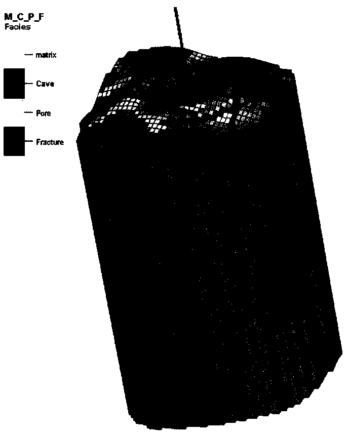
[0067] Figure 5 A schematic diagram of the distribution of reservoirs near Well W is shown according to an embodiment of the present invention. Image 6 A schematic diagram of the distribution of permeability properties of unfilled caves according to an embodiment of the present invention is shown. Figure 7 A schematic diagram of water saturation distribution of an unfilled cave according to an embodiment of the present invention is shown. Figure 8 A schematic diagram of a water cut fitting curve of well W according to an embodiment of the present invention is shown.
[0068] Such as Figure 5-Figure 8 As shown, taking a single well model of a fractured-cavity reservoir as an example, the model size is 31×39×70, the total number of grids is 84,000, the grid steps in the X and Y directions are both 20 m, and the grid steps in the Z direction are 3m ~ 5m. Well W is located at the intersection of faults, with well-developed karst caves, and the production interval is a kar...
PUM
| Property | Measurement | Unit |
|---|---|---|
| Density | aaaaa | aaaaa |
Abstract
Description
Claims
Application Information
 - R&D
- Intellectual Property
- Life Sciences
- Materials
- Tech Scout
- Unparalleled Data Quality
- Higher Quality Content
- 60% Fewer Hallucinations
Browse by: Latest US Patents, China's latest patents, Technical Efficacy Thesaurus, Application Domain, Technology Topic, Popular Technical Reports.
© 2025 PatSnap. All rights reserved.Legal|Privacy policy|Modern Slavery Act Transparency Statement|Sitemap|About US| Contact US: help@patsnap.com