Gasification and incineration method of moving grate gasification and incineration integrated furnace

A technology for moving grate and flue gas, applied in incinerators, combustion methods, combustion types, etc., can solve problems such as affecting combustion efficiency and inability to use heat each other

Inactive Publication Date: 2019-03-22
浙江君华智慧物联科技有限公司
View PDF6 Cites 0 Cited by
  • Summary
  • Abstract
  • Description
  • Claims
  • Application Information

AI Technical Summary

Problems solved by technology

[0005] In the prior art, there is a transitional slagging section between the gasifier and the embering furnace, and the transitional slagging section is provided with an openable and closable isolation door. Since the gasifier and the embering furnace are relatively independent, the slagging generated by material combustion The heat cannot be used mutually, which affects the efficiency of combustion

Method used


Image

  • Gasification and incineration method of moving grate gasification and incineration integrated furnace
  • Gasification and incineration method of moving grate gasification and incineration integrated furnace
  • Gasification and incineration method of moving grate gasification and incineration integrated furnace

Examples


Embodiment Construction

[0037] In order to further explain the technical means and effects of the present invention to achieve the intended purpose of the invention, the specific implementation, structure, features and effects of the present invention will be described in detail below in conjunction with the accompanying drawings and preferred embodiments.

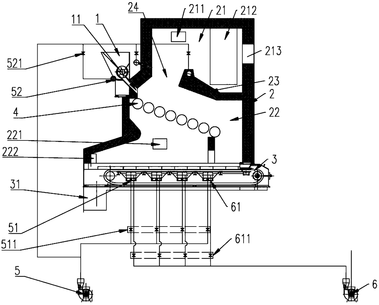
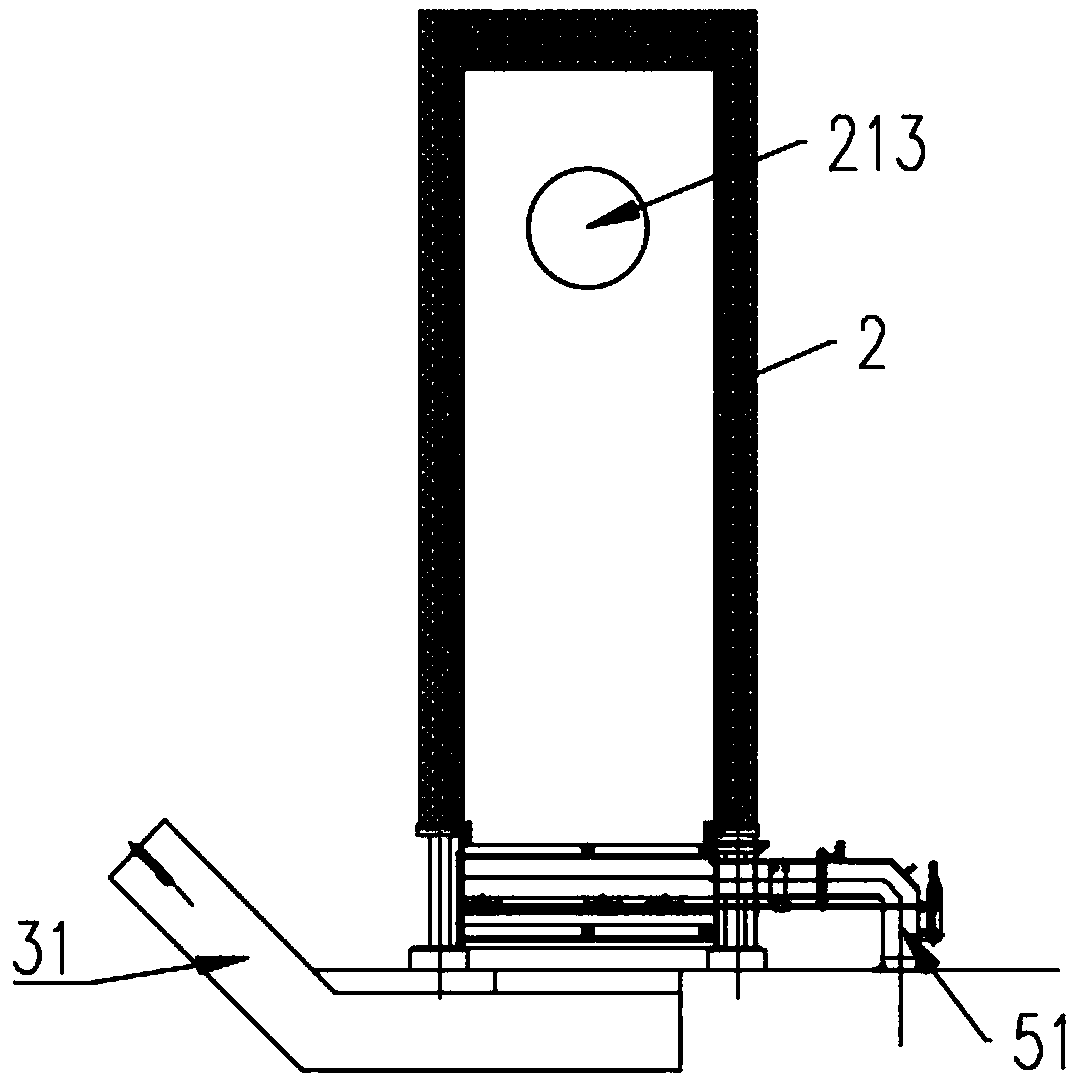
[0038] figure 2 Shown is a schematic structural view of the integrated mobile furnace exhaust gasification and incineration furnace according to the first embodiment of the present invention. image 3 shown as figure 2 The right view of the mobile furnace exhaust gasification incineration integrated furnace. See figure 2 , image 3 , the gasification and incineration method of the mobile furnace exhaust gasification and incineration integrated furnace according to the first embodiment of the present invention includes: a first feeding device 1, a furnace 2, and a lower moving grate 3 arranged below the furnace 2, which also includes A part...


PUM


Abstract

The invention provides a gasification and incineration method of a moving grate gasification and incineration integrated furnace. A first feeding device, a hearth, a lower moving grate arranged belowthe hearth and a partition plate used for separating the hearth into a lower portion gasification and combustion cavity and an upper portion combustion cavity are included. A flue gas flow through hole is formed in the position, close to a discharging port of the first feeding device, of the partition plate, and the discharging port of the first feeding device is located at the middle portion of the hearth. The lower portion gasification and combustion cavity and the flue gas flow through hole are provided with first air inlets and second air inlets correspondingly. The method includes the steps that the first feeding device is controlled to convey materials towards the interior of the hearth; the materials move towards an upper moving grate and absorb heat of flue gas flowing to the fluegas flow through hole, and drying and gasification are conducted; combustion supporting air is injected into the lower portion gasification and combustion cavity through the first air inlets so that the materials moving to the upper moving grate can be combusted; and combustion supporting air is injected into the glue gas flow through hole through the second air inlets so that the temperature of the flue gas in the flue gas flow through hole can be increased, and pyrolysis of tar in the flue gas can be achieved. The method has the beneficial effects that combustion is more sufficient, and efficiency is high.

Description

technical field [0001] The invention relates to the field of solid waste incineration treatment, in particular to a gasification and incineration method for a mobile furnace exhaust gasification and incineration integrated furnace. Background technique [0002] The existing waste treatment technologies mainly include incineration, sanitary landfill, composting, and waste recycling. Among the conventional waste treatment technologies, incineration has the advantages of obvious reduction effect, complete harmlessness, small land occupation, utilization of waste heat energy, and less secondary pollution, which meets the strategic requirements of my country's sustainable development. However, with the continuous improvement of environmental protection requirements at home and abroad, how to strengthen the control of secondary pollution is particularly important. Therefore, waste pyrolysis and gasification incineration technology is gradually pushed to the road of industrial app...

Claims


Application Information

Patent Timeline
Patent Type & Authority Applications(China)
IPC IPC(8): F23G5/027F23G5/44F23G5/46F23G5/50
CPCF23G5/002F23G5/027F23G5/44F23G5/444F23G5/46F23G5/50F23G2201/303F23G2203/105F23G2206/203Y02E20/12
Inventor 王改李福金沈玉华席向东刘东平张又红刘小六
Owner 浙江君华智慧物联科技有限公司
Why Eureka
Try Eureka