Step variable cross-section rotor flywheel energy storage system with hybrid support of permanent magnet bearings and electromagnetic bearings

A technology of electromagnetic bearing and permanent magnetic bearing, which is applied in the field of flywheel energy storage, can solve the problems of poor structure compactness of the flywheel energy storage system, increase the axial length of the flywheel rotor, and affect the dynamic characteristics of the rotor, so as to improve the rotor dynamics Features, compact system space structure size, compact structure effect

Pending Publication Date: 2019-03-22
HARBIN ELECTRIC CO LTD
View PDF0 Cites 1 Cited by
  • Summary
  • Abstract
  • Description
  • Claims
  • Application Information

AI Technical Summary

Problems solved by technology

If the flywheel energy storage system is installed with an inner rotor motor and supported by multiple magnetic suspension bearings, the axial length of the flywh

Method used


Image

  • Step variable cross-section rotor flywheel energy storage system with hybrid support of permanent magnet bearings and electromagnetic bearings
  • Step variable cross-section rotor flywheel energy storage system with hybrid support of permanent magnet bearings and electromagnetic bearings
  • Step variable cross-section rotor flywheel energy storage system with hybrid support of permanent magnet bearings and electromagnetic bearings

Examples


Embodiment

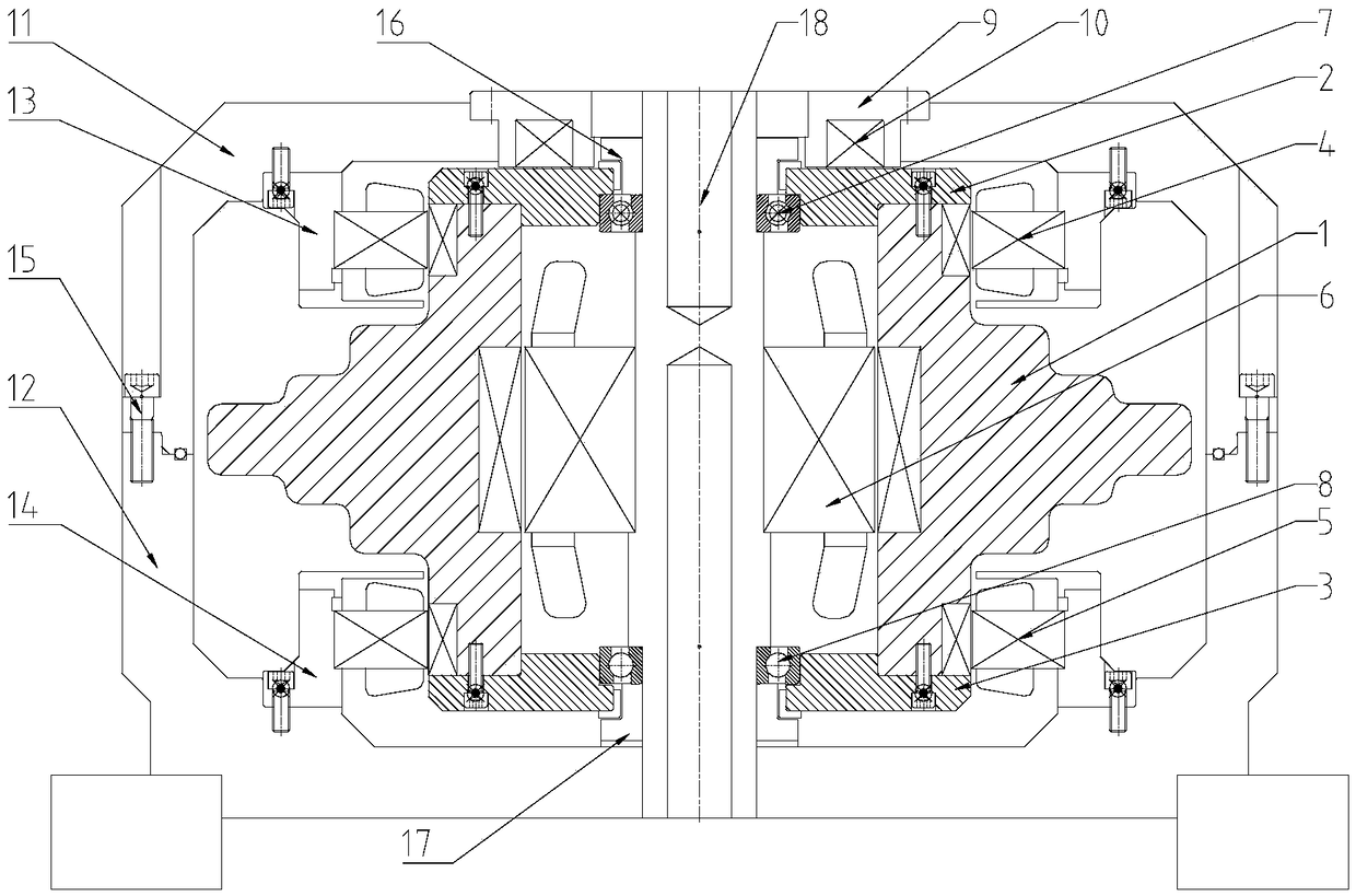
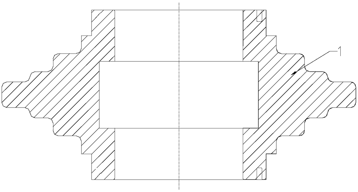
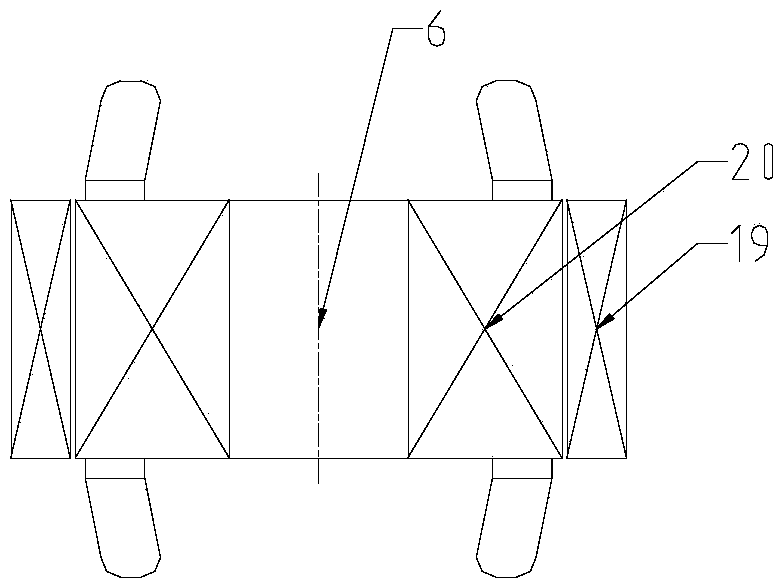
[0032] Example: see Figure 1 to Figure 5 , the energy storage system of the stepped variable cross-section rotor flywheel in this embodiment, which is supported by a mixture of permanent magnetic bearings and electromagnetic bearings, includes an energy storage and conversion part, a rotor support part and an auxiliary part; wherein, the energy storage and conversion part includes: a flywheel rotating body, an integrated Electric / power generation reciprocal bidirectional motor; the rotor support part includes: upper radial electromagnetic bearing 4, lower radial electromagnetic bearing 5, permanent magnet thrust bearing 9, upper auxiliary bearing 7, lower auxiliary bearing 8; auxiliary part includes: shell body and mandrel 18.

[0033] Among them, the integrated electric / power generation reciprocal bidirectional motor selects the outer rotor permanent magnet synchronous motor 6, the permanent magnet thrust bearing 9, the upper auxiliary bearing 7, the outer rotor permanent magn...


PUM


Abstract

The invention relates to a step variable cross-section rotor flywheel energy storage system with hybrid support of permanent magnet bearings and electromagnetic bearings, and belongs to the technicalfield of flywheel energy storage. The step variable cross-section rotor flywheel energy storage system with hybrid support of permanent magnet bearings and electromagnetic bearings solves the problemthat the axial length of a flywheel rotor existing in an existing flywheel energy storage system affects the dynamic mechanical characteristics of the rotor and leads to low compactness of the flywheel energy storage system structure. For the step variable cross-section rotor flywheel energy storage system with hybrid support of a permanent magnet bearing and an electromagnetic bearing, a permanent magnet thrust bearing, an upper auxiliary bearing, an outer rotor permanent magnet synchronous motor and a lower auxiliary bearing are mounted on a mandrel, and the upper end and the lower end of aflywheel rotating body are in a clearance fit state with an upper auxiliary bearing and a lower auxiliary bearing; a gap is formed between the permanent magnet thrust bearing and the upper end surfaceof the flywheel rotating body; the outer rotor permanent magnet synchronous motor is arranged in the flywheel rotating body to drive the flywheel rotating body to rotate; an upper radial electromagnetic bearing and a lower radial electromagnetic bearing are fixedly arranged on a housing; and the radial electromagnetic bearings are in a non-contact state with the outer wall of the flywheel rotating body; and the flywheel body has a step-variable cross-sectional structure. The rotor system of the step variable cross-section rotor flywheel energy storage system with hybrid support of permanent magnet bearings and electromagnetic bearings is compact in structure and enhances the characteristic of rotordynamics.

Description

technical field [0001] The invention relates to a flywheel energy storage system, in particular to a flywheel energy storage system with a stepped variable cross-section rotor supported by a mixture of permanent magnetic bearings and electromagnetic bearings, and belongs to the technical field of flywheel energy storage. Background technique [0002] As a flexible and adjustable active power source, the flywheel energy storage system actively participates in the dynamic behavior of the system, and can shorten the transient transition process after the disturbance is eliminated, so that the system can quickly return to a stable state. The flywheel energy storage system is mainly composed of flywheel rotors, bearings, integrated electric / power generation reciprocal bidirectional motors, electronic power converters, etc. The integrated electric / power generation reciprocal bidirectional motor realizes the conversion of electric energy and high-speed flywheel mechanical energy. ...

Claims


Application Information

Patent Timeline
IPC IPC(8): H02K7/02H02K7/09H02K7/08
CPCH02K7/025H02K7/086H02K7/09Y02E60/16
Inventor 赵宇兰董爱华张春伟周佳亮车东光
Owner HARBIN ELECTRIC CO LTD
Why Eureka
Try Eureka