Convex-convex engaged pure rolling helical bevel gear mechanism for cross shaft transmission

A technology of spiral bevel gears and cross shafts, which is applied in the field of bevel gear transmissions, can solve the problems of uncertain value of coincidence degree of transmission pairs, inability to realize strict design of coincidence degree, and unfavorable load uniform distribution, etc.

A technology of spiral bevel gears and cross shafts, which is applied in the field of bevel gear transmissions, can solve the problems of uncertain value of coincidence degree of transmission pairs, inability to realize strict design of coincidence degree, and unfavorable load uniform distribution, etc.

CN108533683AInactive Publication Date: 2018-09-14CHINA UNIV OF GEOSCIENCES (WUHAN)

Image

  • Convex-convex engaged pure rolling helical bevel gear mechanism for cross shaft transmission
  • Convex-convex engaged pure rolling helical bevel gear mechanism for cross shaft transmission
  • Convex-convex engaged pure rolling helical bevel gear mechanism for cross shaft transmission

Examples


Embodiment 1

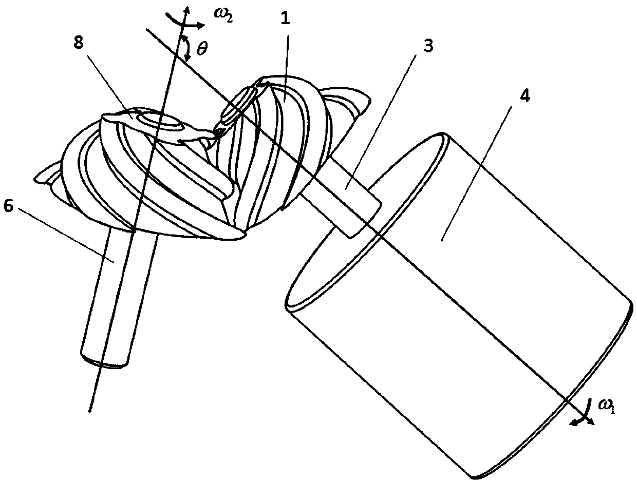
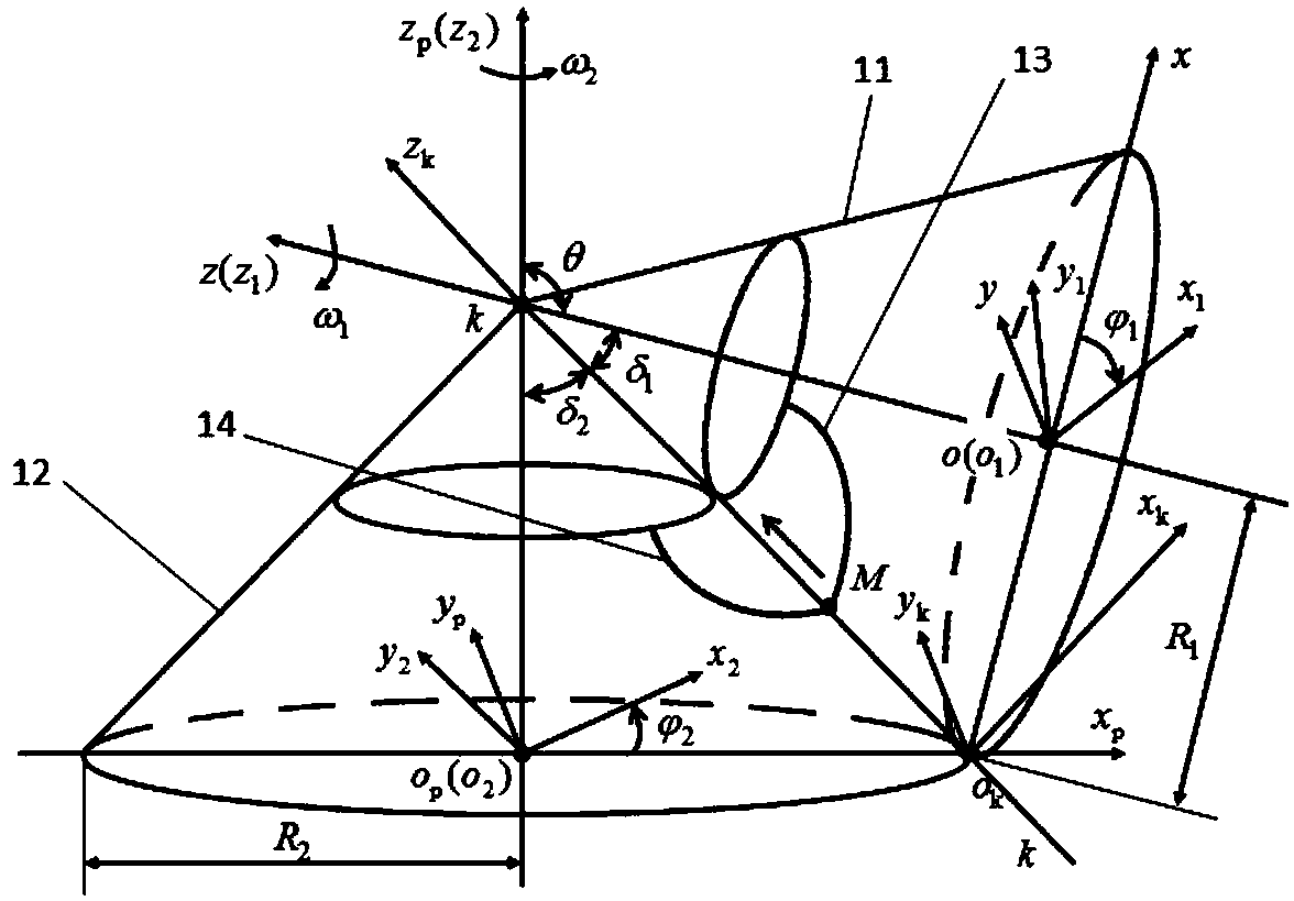
[0112] Embodiment 1: The present invention provides a convex-convex meshing pure rolling spiral bevel gear mechanism for cross shaft transmission, which is applied to the transmission with a transmission ratio of 1 between two cross shafts in the plane, and its structure is as follows figure 1 As shown, it includes a small wheel 1 and a large wheel 8. The small wheel 1 and the large wheel 8 form a pair of transmission pairs. The small wheel 1 is connected to the input shaft 3, and the large wheel 8 is connected to the output shaft 6, that is, the large wheel 8 is connected to the output shaft 6 through the output shaft 6. The driven load is connected; the axes of the small wheel 1 and the large wheel 8 intersect, and the angular velocity vector angle between the small wheel and the large wheel is θ, and θ=2π / 3 radians (rad) in this example. figure 2 It is a schematic diagram of the spatial coordinate system of the convex-convex meshing pure rolling helical bevel gear mechanism...

Embodiment 2

[0214] Embodiment 2: The convex-convex meshing pure rolling spiral bevel gear mechanism of the present invention for cross shaft transmission is applied to the speed-up transmission between two vertical cross shafts, at this time θ=π / 2 radians (rad). Such as Figure 10 As shown, the large wheel 8 is used to connect the input shaft 3, and the small wheel 1 is connected to the output shaft 6, that is, the small wheel 1 is connected to the driven load through the output shaft 6; the axes of the small wheel 1 and the large wheel 8 are perpendicular to each other, and at this time they The included angle of angular velocity is θ=π / 2 radians (rad). In this embodiment, there are eight spiral arc teeth 7 on the bull wheel 8, and four spiral arc teeth 2 on the small wheel 1. When the input shaft 3 drives the bull wheel 8 to rotate, the design coincidence degree ε=4 / 3. Because when the bull wheel 8 and the small wheel 1 are installed, the spiral arc tooth 7 on the bull wheel 8 is engag...


PUM


Abstract

The invention provides a convex-convex engaged pure rolling helical bevel gear mechanism for cross shaft transmission. The convex-convex engaged pure rolling helical bevel gear mechanism comprises a pinion and a main gear which form a transmission pair; the pinion is fixedly connected with a driver through an input shaft; the main gear is connected with an output shaft; the axis of the pinion is intersected with the axis of the main gear; the conical outer surface of the pinion is provided with n1 helical circular arc teeth which are distributed uniformly; the center lines of all helical circular arc teeth all are equal-lift conical helical lines; a transition fillet is arranged between the helical circular arc teeth and the conical outer surface of the pinion; the conical outer surface ofthe main gear is provided with n2 helical circular arc teeth which are distributed uniformly; the center lines of all helical circular arc teeth all are equal-lift conical helical lines; a transitionfillet is arranged between the helical circular arc teeth and the conical outer surface of the main gear; and the helical circular arc teeth of the pinion and the helical circular arc teeth of the main gear are engaged in a point-contact pure rolling engagement transmission manner. The convex-convex engaged pure rolling helical bevel gear mechanism provided by the invention has the beneficial effects of being high in transmission efficiency, large in overlap ratio, high in bearing capacity and widely applied to the fields of tiny machinery, micro machinery and general machinery which are difficult to lubricate.

Description

technical field [0001] The invention relates to a bevel gear transmission, in particular to a convex-convex meshing pure rolling helical bevel gear mechanism for cross shaft transmission. Background technique [0002] As the core basic components of machinery, gears are widely used in machine tools, automobiles, robots, wind power, coal mines, aerospace and other equipment manufacturing fields and the main battlefield of the national economy. Their performance directly determines the quality of major equipment and high-end industrial products. performance and reliability. [0003] At present, the main problem facing my country's gear industry is the obvious lack of design and manufacturing capabilities for high-efficiency, large-carrying capacity, lightweight, and high-reliability high-performance gear products. The traditional spur gears, helical gears and bevel gear pairs widely used in the field of industrial production and manufacturing have never completely solved the ...

Claims


Application Information

Patent Timeline
14 Sep 2018
Publication
CN108533683A
IPC
F16H1/14; F16H55/17; F16H55/08; G06F17/50
CPC
F16H1/14; F16H55/08; F16H55/17; F16H2055/0866; G06F30/17; G06F30/367
Inventors
陈祯; 丁华锋