Protection mechanism for solar photovoltaic panel

A solar photovoltaic panel and protection mechanism technology, applied in the photovoltaic field, can solve the problems of increasing maintenance cost of photovoltaic power generation, lack of photovoltaic panel protection mechanism, affecting the normal use of photovoltaic panels, etc., so as to improve service life, improve work efficiency, and ensure stable and normal effect

Inactive Publication Date: 2019-03-22
贺基乾
View PDF7 Cites 9 Cited by
  • Summary
  • Abstract
  • Description
  • Claims
  • Application Information

AI Technical Summary

Problems solved by technology

However, the easy-to-adjust solar photovoltaic panel connection device mentioned in this patent document lacks a mechanism for protecting the photovoltaic panel, and cannot adapt to the weather conditions of strong wind and sand in the northwest region, which will seriously affect the performance of the photovoltaic panel. Normal use, and to a certain extent, will increase the maintenance cost of photovoltaic power generation

Method used


Image

  • Protection mechanism for solar photovoltaic panel
  • Protection mechanism for solar photovoltaic panel
  • Protection mechanism for solar photovoltaic panel

Examples


Embodiment 1

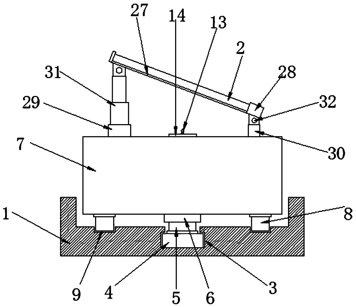
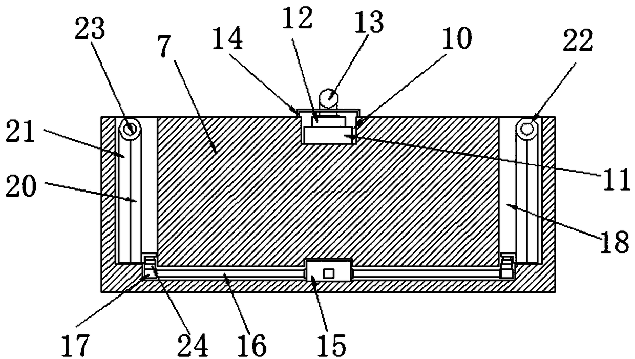
[0032] Embodiment one, such as Figure 1-3As shown, a protection mechanism for solar photovoltaic panels according to an embodiment of the present invention includes a base 1 and a photovoltaic panel 2, the top of the base 1 is provided with a groove-3, and the inner bottom of the groove-3 is A motor one 4 is installed at the top of the motor one 4, a rotating shaft 5 is installed on the top of the rotating shaft one 5, a fixed shaft 6 is installed on the top of the rotating shaft 5, a support seat 7 is installed on the top of the fixed shaft 6, and the support seat 7 The bottom of 7 is symmetrically equipped with a sliding support block 8, and the base 1 is provided with an annular groove 9 suitable for the sliding support block 8, and the top of the support base 7 is provided with a groove 2 10, the A controller 11 is installed at the inner bottom of the groove two 10, a sensor 12 is installed on the top of the controller 11, an inductor 13 is installed on the top of the sen...

Embodiment 2

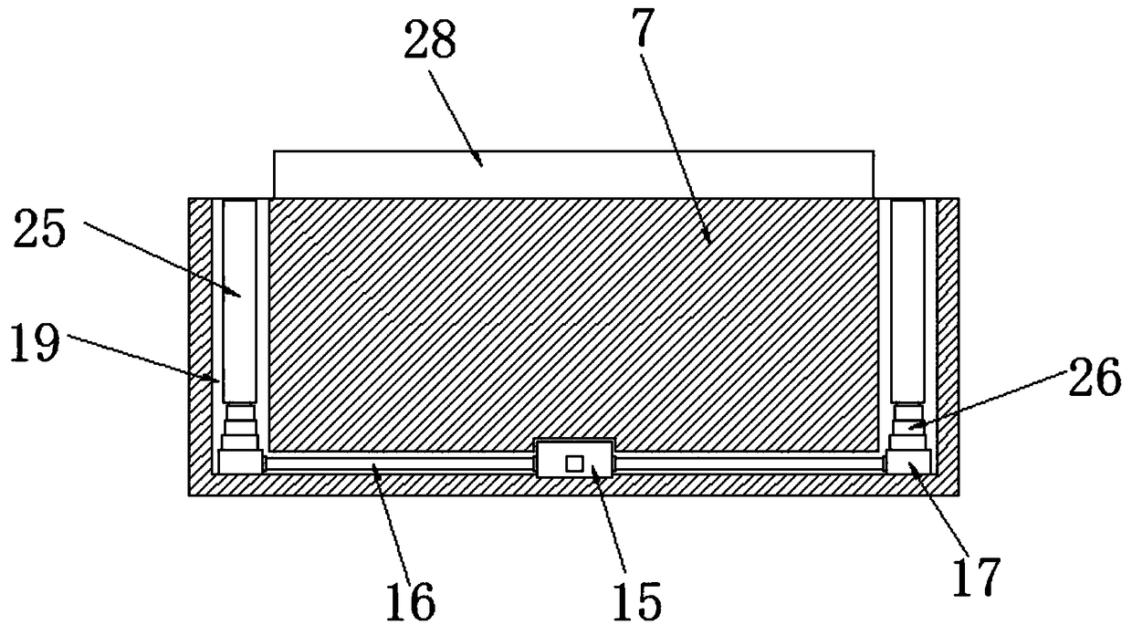
[0033] Embodiment two, such as Figure 1-3 As shown, the controller 11 is connected to the first motor 4, the hydraulic cylinder 15 and the second motor 23 through a wireless control circuit;

Embodiment 3

[0034] Embodiment three, such as figure 1 As shown, the bottom of the photovoltaic panel 2 is provided with a mounting plate 27, and one side of the mounting plate 27 is provided with a mounting block 28; the top of the support base 7 is equipped with a cylinder 29 and a fixed block 30, and the cylinder A telescopic rod 31 is installed on the top of 29, and the telescopic rod 31 and the top of the fixed block 30 are respectively movably connected with the bottom of the mounting plate 27 and the mounting block 28 through a movable shaft 32;


PUM


Abstract

The invention discloses a protection mechanism for a solar photovoltaic panel. The protection mechanism comprises a base and the photovoltaic panel, wherein a groove 1 is formed in the top part of thebase, a motor 1 is installed at the bottom end inside the groove 1, the top part of the motor 1 is provided with a rotating shaft 1, the top part of the rotating shaft 1 is provided with a fixed shaft, the top part of the fixed shaft is provided with a supporting base, the bottom part of the supporting base is symmetrically provided with sliding support blocks, an annular groove matched with thesliding support blocks is formed in the base, a groove 2 is formed in the top part of the supporting base, a controller is installed at the bottom end inside the groove 2, the top part of the controller is provided with a sensor, the top part of the sensor is provided with an inductor, the top part of the groove 2 is provided with a cover plate, the inductor penetrates the cover plate and extendsabove the cover plate, a hydraulic cylinder is installed at the bottom end inside the supporting base, and four side edges of the hydraulic cylinder are provided with transmission rods.

Description

technical field [0001] The invention relates to the field of photovoltaic technology, in particular to a protection mechanism for solar photovoltaic panels. Background technique [0002] Photovoltaic: It is the abbreviation of solar photovoltaic power generation system. It is a new type of power generation system that uses the photovoltaic effect of solar cell semiconductor materials to directly convert solar radiation energy into electrical energy. There are two modes of independent operation and grid-connected operation; at the same time , the classification of solar photovoltaic power generation systems, one is centralized, such as large-scale Northwest ground photovoltaic power generation systems; the other is distributed, such as industrial and commercial enterprise factory roof photovoltaic power generation systems, residential roof photovoltaic power generation systems; Fixed installation is not conducive to better absorption and conversion of solar energy. At the sam...

Claims


Application Information

Patent Timeline
Patent Type & Authority Applications(China)
IPC IPC(8): H02S20/30H02S30/00F24S30/425
CPCH02S20/30H02S30/00Y02E10/50
Inventor 贺基乾
Owner 贺基乾
Why Eureka
Try Eureka