Method and device for adaptively adjusting voltage and frequency

A technology of self-adaptive voltage and frequency adjustment, applied in the direction of electrical components, automatic power control, etc., can solve the problems of complex calibration, slow control speed, high power consumption, etc., to improve consistency, rapid frequency adjustment, and stability. omitted effect

Active Publication Date: 2019-03-22
FUZHOU ROCKCHIP SEMICON
View PDF6 Cites 8 Cited by
  • Summary
  • Abstract
  • Description
  • Claims
  • Application Information

AI Technical Summary

Problems solved by technology

[0020] For this reason, it is necessary to provide a technical solution for adaptive voltage and frequency adjustment to solve the problems of complex calibration, large power consumption, and slow control speed in existing power supply voltage adjustment methods.

Method used


Image

  • Method and device for adaptively adjusting voltage and frequency
  • Method and device for adaptively adjusting voltage and frequency
  • Method and device for adaptively adjusting voltage and frequency

Examples


Embodiment 1

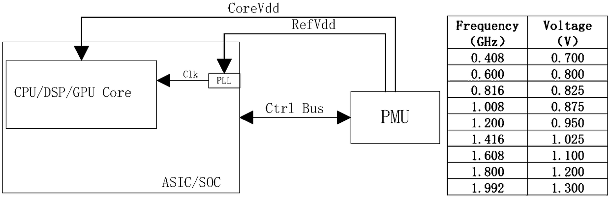
[0101] Embodiment one: when (F r -F n ) / F c ≥2 N-1When , an AC signal is generated, indicating that the actual output frequency of the ring oscillator is lower than the design expectation, and it also indicates that the actual performance of the chip is lower than the design expectation. The AC signal acts as a FastDown signal to quickly reduce the output frequency of the PLL, making F Clkout clkin , that is, let the PLL output frequency drop rapidly, and make F Clkout It is equal to the frequency of the ring oscillator; AC is also used as a power supply voltage up-regulation signal, and CoreVdd is increased accordingly until the voltage reaches enough to make the counter no longer generate AC signals.

Embodiment 2

[0102] Embodiment two: when (F n -F r ) / F c ≥2 N-1 When the BS signal is generated, it means that the actual output frequency of the ring oscillator is higher than the expected frequency, and the actual performance of the chip is higher than expected. The BS signal is used as a down-regulation signal of CoreVdd until the counter no longer generates the BS signal.

Embodiment 3

[0103] Embodiment three: when |F r -F n | / F c N-1 When , no BS or AC signal is generated, indicating that the actual performance of the chip meets the design expectations, and there is no need to adjust the frequency and voltage.

[0104] In summary, when debugging the chip, you only need to set an expected frequency that needs to be achieved, and set Clkin (the frequency received by the PLL clock circuit) to the required frequency. When the process, power supply or temperature cause the ring oscillator to When there is a deviation between the oscillation frequency and the design expectation, the device can adaptively adjust the voltage frequency to meet the performance requirements of the processor.

[0105] Such as Figure 8 As shown in FIG. 1 , it is a flow chart of an adaptive voltage-frequency adjustment method related to an embodiment of the present invention. The method is applied to an adaptive voltage frequency adjustment device, and the device includes a processo...


PUM


Abstract

The invention provides a method and a device for adaptively adjusting a voltage and a frequency. In practical application, a system software only needs to set a target frequency of an ASIC / SOC chip according to a performance demand; when the supply voltage of the chip fails to meet the demand of the target frequency, the scheme can automatically adjust a working frequency to a frequency adapted toa current chip process, a power supply voltage and a temperature, and send a corresponding control signal to adjust a output voltage of a power supply module until the power supply voltage is matchedto the target frequency. The scheme does not cause digital logic errors by the insufficient power supply voltage, and can also automatically adjust the PLL output frequency and the power supply voltage according to differences of the chip process, the voltage, and the temperature, thereby improving the consistency and the stability of the chip, and omitting the waiting time for adjusting the power supply voltage, so that the frequency of the chip is adjusted more rapidly, and the purposes of rapidly changing the frequency and the voltage and saving the power consumption are achieved.

Description

technical field [0001] The invention relates to the field of computer technology security, in particular to an adaptive voltage frequency adjustment method and device. Background technique [0002] With the improvement of integrated circuit performance and technology, the problem of circuit power consumption has become more and more prominent. The power consumption of ASIC / SOC mainly includes two types: static power consumption and dynamic power consumption. Here, the dynamic power consumption is mainly considered. The power consumption generated when the logic state of the circuit is flipped is dynamic power consumption, which is mainly composed of switching power consumption and short-circuit power consumption. The power consumption generated when the circuit has no state reversal is static power consumption, which mainly refers to the power consumption generated by the leakage current of the transistor. [0003] Such as figure 1 and figure 2 As shown, in the basic lo...

Claims


Application Information

Patent Timeline
IPC IPC(8): H03L7/099
CPCH03L7/0995
Inventor 郑发耀
Owner FUZHOU ROCKCHIP SEMICON
Why Eureka
Try Eureka