Elevator control device

A technology for elevator control devices and accumulators, which is applied in the direction of AC motor control, control systems, electrical components, etc., to achieve the effects of reducing costs, reducing requirements for model selection, and reducing instantaneous current

Active Publication Date: 2019-03-26
SHANGHAI MITSUBISHI ELEVATOR CO LTD
View PDF5 Cites 2 Cited by
  • Summary
  • Abstract
  • Description
  • Claims
  • Application Information

AI Technical Summary

Problems solved by technology

Therefore, it is not feasible to directly use the AC contactor in the above-mentioned elevator device

Method used


Image

  • Elevator control device
  • Elevator control device

Examples


Embodiment 1

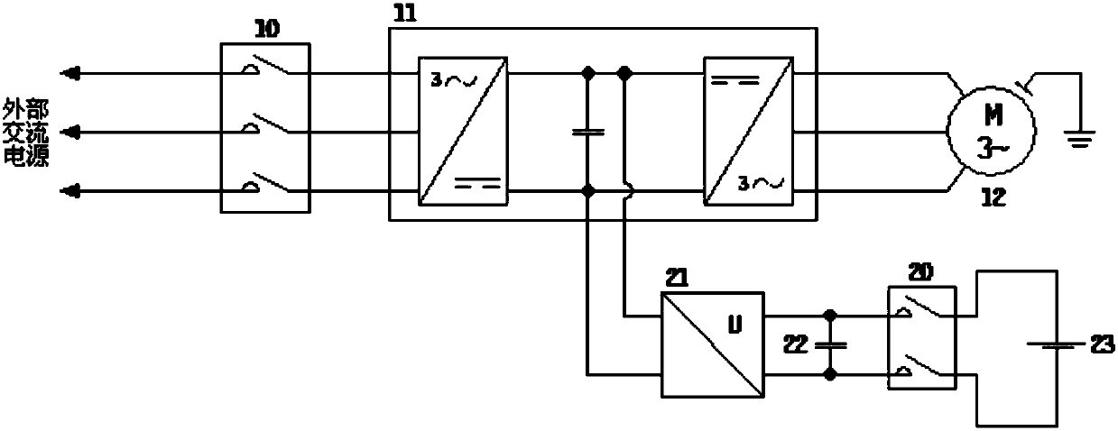
[0053] Such as figure 1 As shown, the elevator control device includes a second contactor 20, a frequency converter 11, a motor 12, a DC converter 21, a buffer capacitor 22, and an accumulator 23.

[0054] The frequency converter 11 includes a rectifier 111 and an inverter 112 for supplying power to the motor 12 and driving the motor to run;

[0055] The input terminal of the rectifier 111 is connected to an external AC power source, and a DC voltage is output to the input terminal of the inverter 112;

[0056] The inverter 112 inverts the DC voltage at its input end into an AC voltage to supply power to the motor 12;

[0057] The high-voltage terminal of the DC converter 21 is connected to the input terminal of the inverter 112;

[0058] The second contactor 20 is connected between the low-voltage end of the DC converter 21 and the accumulator 23;

[0059] The buffer capacitor 22 is disposed between the DC converter 21 and the second contactor 20, and both ends of the buffer capacitor...

Embodiment 2

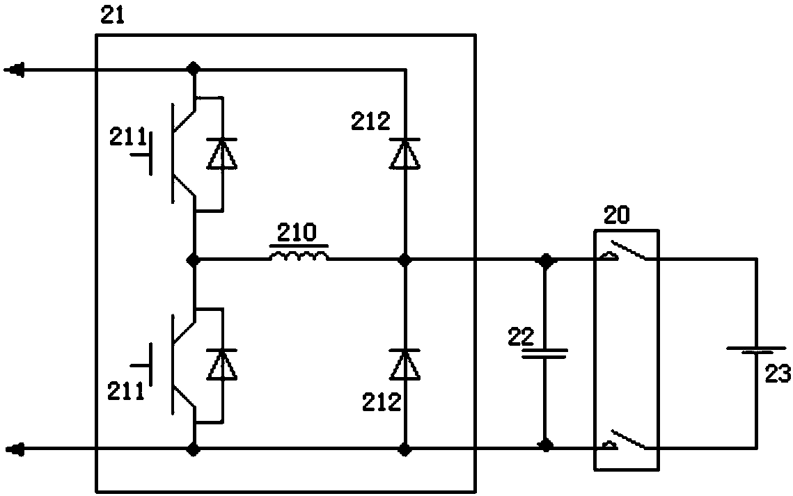
[0065] The elevator control device based on the first embodiment, such as figure 2 As shown, the DC converter 21 includes two power switch tubes 211, two diodes 212, and a built-in inductor 210;

[0066] The power switch tube 211 includes a control terminal, a first terminal, and a second terminal. The conduction or cut-off between the first terminal and the second terminal is controlled by a voltage signal applied at the control terminal;

[0067] The first terminal of the first power switch tube 211 is connected to the positive input terminal of the inverter 112;

[0068] The second end of the first power switch tube 211 is connected to the first end of the second power switch tube 211;

[0069] The second terminal of the second power switch tube 211 is connected to the negative input terminal of the inverter 112;

[0070] The negative terminal of the first diode 212 is connected to the positive input terminal of the inverter 112;

[0071] The negative terminal of the second diode 212 ...


PUM


Abstract

The invention discloses an elevator control device. The input end of a rectifier is connected with an external alternating current power supply, and direct current voltage is output to the input end of an inverter. The inverter inverts the direct current voltage at the input end into alternating current voltage to supply power to a motor. The high voltage end of a direct current converter is connected with the input end of the inverter. A second contactor is connected between the low voltage end of the direct current converter and an accumulator. A buff capacitor is disposed between the directcurrent converter and the second contactor, and the two ends of the buffer capacitor are separately connected with the positive and negative ends of the low voltage end of the direct current converter. The elevator control device has low cost.

Description

Technical field [0001] The invention relates to elevator driving and control technology, in particular to an elevator control device. Background technique [0002] As the process of urbanization continues to deepen, more and more buildings begin to rise in the city, and the urban architectural space is continuously extending in the vertical direction, which has also resulted in the steadily increasing use of elevators. Although elevators provide great convenience for people's vertical transportation in buildings, they also consume a lot of electric energy. [0003] When the elevator is running, the traction motor is in the state of regenerative power generation under heavy load downward, light load upward, and deceleration. At this time, the elevator not only does not consume electric energy, but instead converts part of the potential energy of the elevator system into electric energy, which is fed back to the elevator system in. At present, the use of energy storage devices such...

Claims


Application Information

Patent Timeline
Patent Type & Authority Applications(China)
IPC IPC(8): B66B1/34H02P27/06
CPCB66B1/34H02P27/06
Inventor 刘文晋张磊
Owner SHANGHAI MITSUBISHI ELEVATOR CO LTD
Why Eureka
Try Eureka