
Tunnel drilling robot and construction drilling method thereof

A technology of robots and drilling mechanisms, applied in drilling equipment and methods, drilling equipment, directional drilling, etc., can solve the problems of high scrap rate of drill bits, complex equipment, low drilling efficiency, etc., to reduce the probability of rebar, reduce Dust concentration, simple structure effect

Pending Publication Date: 2019-03-26
NAT INST CORP OF ADDITIVE MFG XIAN
View PDF2 Cites 7 Cited by
  • Summary
  • Abstract
  • Description
  • Claims
  • Application Information

AI Technical Summary

Problems solved by technology

[0006] In order to solve the problems of low drilling efficiency, high scrap rate of drill bits and complex equipment, the present invention provides a tunnel drilling robot with simple structure, which can realize automatic drilling construction, has the functions of steel bar avoidance detection and automatic compensation, and further It can also complete the automatic and precise positioning of the axial hole spacing, and can realize the radial adjustment of the position of the side wall of the drilling hole of different types of mounting brackets, and the volume of the equipment can be automatically adjusted. The concrete dust can be effectively removed during the drilling process, and the drilling efficiency can be greatly improved. Reduce labor intensity

Method used


Image

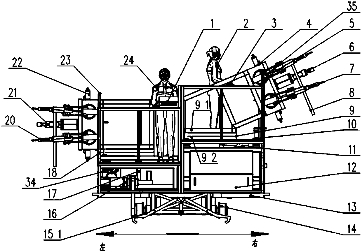
  • Tunnel drilling robot and construction drilling method thereof
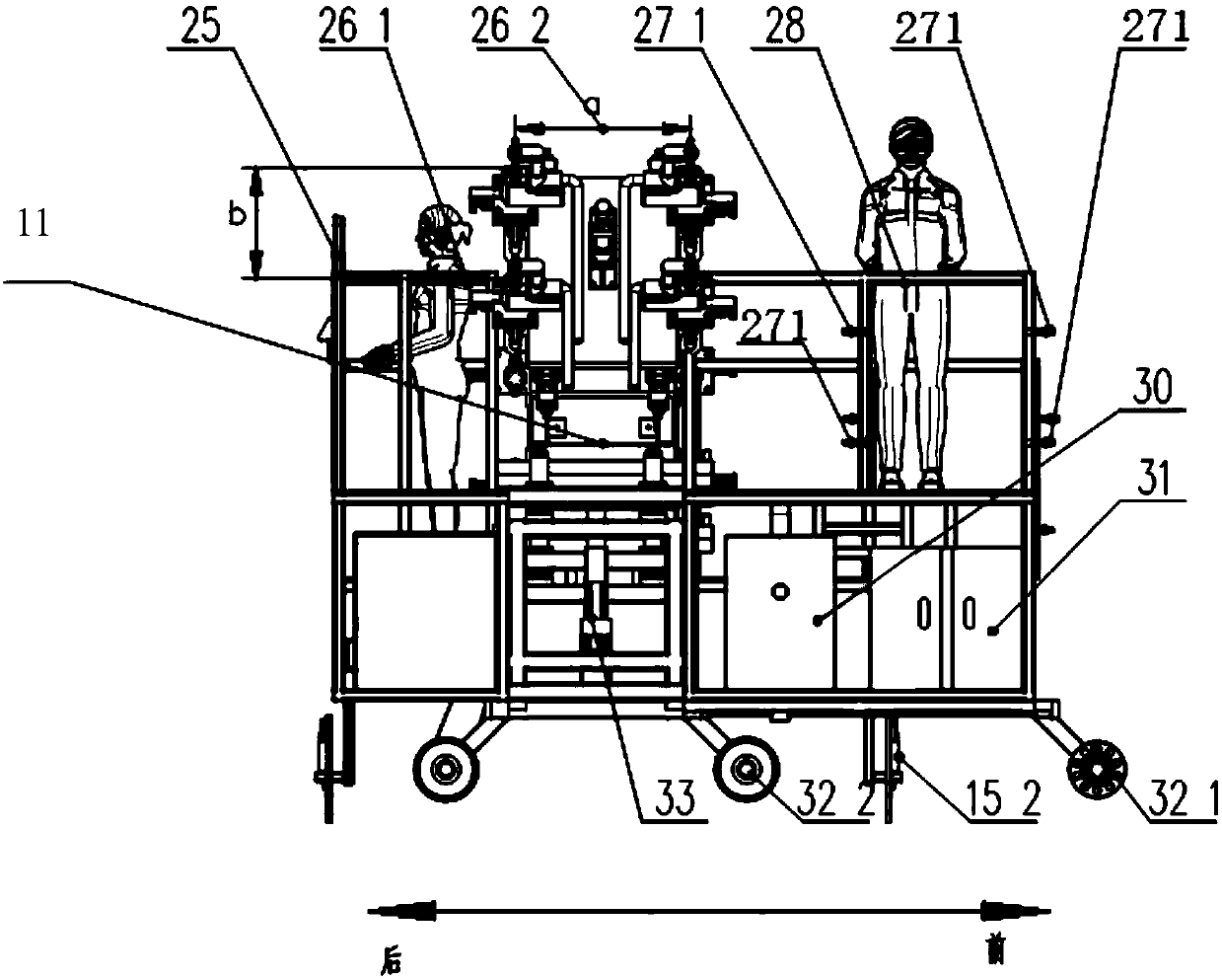
  • Tunnel drilling robot and construction drilling method thereof
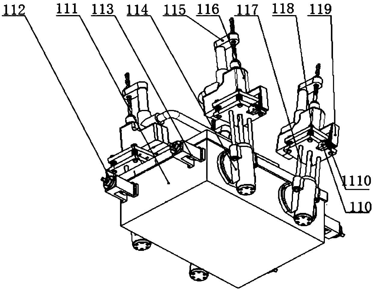
  • Tunnel drilling robot and construction drilling method thereof

Examples


Embodiment Construction

[0053] The present invention will be further described below in conjunction with the accompanying drawings and specific embodiments.

[0054] Such as figure 1 , figure 2 As shown, the present embodiment includes the control system 1, the bottom automatic walking positioning system, the left and right two groups of steel bar automatic detection and compensation systems and the left and right groups of drilling systems. The position of the drilling system is set according to the height of the part to be processed in actual processing. For ease of description, the figure 1 The steel bar automatic detection and compensation system and drilling system on the left are defined as the left steel bar automatic detection and compensation system and the left drilling system, and the steel bar automatic detection and compensation system and drilling system on the right are defined as the right steel bar automatic detection Compensation system and right drilling system.

[0055] The b...


PUM


Abstract

The invention relates to a tunnel drilling robot and a construction drilling method thereof. The tunnel drilling robot comprises a control system, an automatic walking positioning system, n groups ofsteel bar automatic detection and compensation systems, n groups of drilling systems and a power supply system. The steel bar automatic detection and compensation systems each include a servo laser locator, a steel bar detector, a steel bar yielding bracket and a steel bar yielding bracket driver. The steel bar detector is used for detecting steel bars at a positioning point of the servo laser locator, and sending detection data to the control system, and the control system controls the steel bar yielding bracket driver to drive the steel bar yielding bracket to move according to the detectiondata of the steel bar detector, the drilling systems each include a drilling bracket disposed on the steel bar yielding bracket and an axial drilling system fixed on the drilling bracket, the axial drilling system includes m drilling mechanisms, and the m drilling mechanisms are arranged in the axial direction and circumferential direction of a tunnel. The problems of low punching efficiency, high drill bit rejection rate and complicated devices are solved.

Description

technical field [0001] The invention relates to a tunnel drilling robot and a construction drilling method thereof. Background technique [0002] In recent years, in order to alleviate the pressure of urban travel, especially to reduce the emission of private car exhaust pollutants in winter and protect the environment, my country has developed a variety of public transportation modes, especially large-scale subway construction. [0003] During the construction of the subway tunnel, it is necessary to drill thousands of sets of installation holes on the tunnel wall along the line direction of the tunnel to install different professional cable supports. [0004] The traditional punching operation is to divide the construction into three processes during the installation and construction of the bracket, namely, setting out wire positioning, drilling, and installing and fixing. During construction, the operators are divided into two groups, with 3-4 people in each group. First...

Claims


Application Information

Patent Timeline
IPC IPC(8): E21B7/02E21B7/04E21B15/04
CPCE21B7/02E21B7/022E21B7/026E21B7/04E21B15/04
Inventor 汤永凯王磊盛晓东刘思延赵纪元
Owner NAT INST CORP OF ADDITIVE MFG XIAN
Learn More