Non-heating environment-friendly humidification device

A humidification device and environmental protection technology, applied in heating methods, air humidification systems, lighting and heating equipment, etc., can solve the problems of high energy consumption, poor environmental protection effect, affecting air humidity, etc., and achieve wide atomization area and atomization efficiency. The effect of high and wide atomization humidification area

Active Publication Date: 2019-03-26
YANCHENG DONGFANG TIANCHENG MACHINERY
View PDF10 Cites 3 Cited by
  • Summary
  • Abstract
  • Description
  • Claims
  • Application Information

AI Technical Summary

Problems solved by technology

Humidifiers are used to solve the problem of indoor humidity. However, the existing humidifiers consume a lot of energy and affect the humidity of the air.
Chinese patent (Notice No. CN207797302U) discloses a candle end face cutting device with drilled candle wicks. Although it can achieve humidification effect, it adopts heating principle and has no directional humidification function, so the environmental protection effect is poor.

Method used


Image

  • Non-heating environment-friendly humidification device
  • Non-heating environment-friendly humidification device
  • Non-heating environment-friendly humidification device

Examples


Embodiment 1

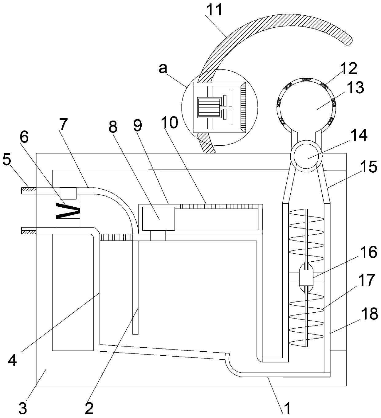
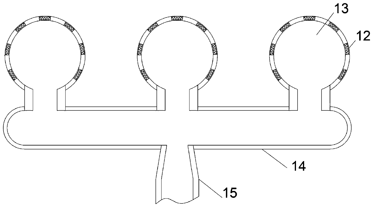
[0019] see figure 1 , image 3 , in an embodiment of the present invention, a non-heating environment-friendly humidifying device, including a vertically arranged support installation cylinder 3, an inclined bottom flow guide installation cylinder 4 is arranged at the inner middle position of the support installation cylinder 3, and the inclined bottom flow guide installation cylinder 4 The upper left end of the upper left end extends to the left through an arc-shaped connecting pipe. The support installation tube 3 is provided with a water inlet guide tube 7, and the support installation tube 3 on the right side of the inclined bottom guide installation tube 4 passes through the U-shaped guide tube 1 vertically upward. A booster guide tube 18 is provided. The upper end of the booster guide tube 18 is provided with a protruding support installation tube 3 and a uniform atomization structure. Structure, the left end of the water inlet diversion pipe 7 protrudes from the suppor...

Embodiment 2

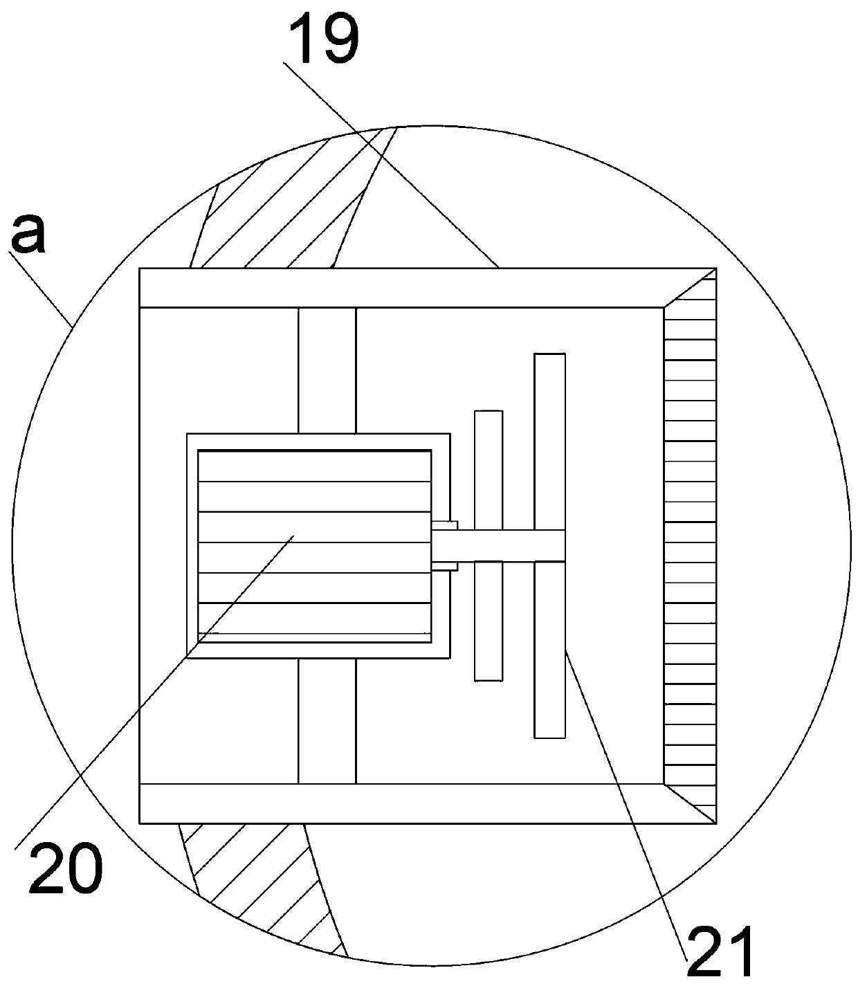
[0021] refer to figure 2 , on the basis of Embodiment 1, the curved surface deflector blowing structure includes a curved surface deflector 11 set to the right at the middle position of the upper end of the support installation cylinder 3, and the left end of the arc deflector 11 is horizontally provided with a blower installation cylinder 19. The inside of the blower installation cylinder 19 is horizontally provided with a blower motor 20 through the guide installation frame. The right end of the blower motor 20 is provided with a variable diameter blower impeller 21 through the motor shaft, and the right end of the blower installation cylinder 19 is vertically provided with a slow flow filter. By starting the blowing motor 20, it drives the variable-diameter blowing impeller 21 to rotate, so that the atomized small droplets can be quickly exported, and the atomized humidification area is wider, because the diameter of the atomized small droplets is obviously smaller than the...


PUM


Abstract

The invention relates to the field of environment-friendly humidification equipment, in particular to a non-heating environment-friendly humidification device. A vertically-arranged support installingbarrel is included. An inclined bottom flow guiding installing barrel is arranged at the middle position in the support installing barrel. The upper left end of the inclined bottom flow guiding installing barrel leftwards stretches out of the support installing barrel through an arc connecting pipe to be provided with a water inlet flow guiding pipe, and the part, on the right side of the inclined bottom flow guiding installing barrel, of the support installing barrel is internally and vertically upwards provided with a pressurizing flow guiding pipe through a U-shaped flow guiding pipe, andstable flow guiding of water energy is achieved through one-way flow guiding. Through two-level pressurizing, water is stably atomized and sprayed out, and the non-heating environment-friendly humidification device is suitable for high-fineness atomization sprayer work. Multi-set atomization is synchronously conducted, the atomization area is wide, and the atomization efficiency is high. Through active air blowing and flow guiding, atomized small liquid drops are rapidly guided out, and the atomization and humidification area is wider. Since the diameter of the atomized small liquid drops is obviously smaller than that of atomization equipment used at present, the atomized small liquid drops are rapidly evaporated for air humidification after being blown out, heating for humidification isnot needed, and energy saving and high efficiency are achieved.

Description

technical field [0001] The invention relates to the field of environment-friendly humidifying equipment, in particular to a non-heating and environment-friendly humidifying device. Background technique [0002] Modern engineering design believes that a good environment brings benefits to the human body and products, especially in factories, production workshops, warehouses, offices and homes, and people pay more and more attention to the control of the environment. For example: indoors are dry in winter, and the air humidity does not reach the standard humidity (40%RH-60%RH). The dry environment will lead to water loss and accelerate the aging of life. Humidity has an important impact on people's life and health. With the improvement of people's living standards, air conditioners are widely used, leading to air-conditioning diseases such as skin tightness, dry mouth and tongue, cough and cold, and air conditioners require a lot of heat exchange, resulting in dry indoor air ...

Claims


Application Information

Patent Timeline
Patent Type & Authority Applications(China)
IPC IPC(8): F24F6/12F24F13/00F24F13/08
CPCF24F6/12F24F13/00F24F13/08F24F13/081
Inventor 文露刘扬李开丽
Owner YANCHENG DONGFANG TIANCHENG MACHINERY
Why Eureka
Try Eureka