Radio frequency testing device and radio frequency testing method

A radio frequency test, radio frequency technology, applied in the direction of measuring devices, printed circuit testing, electronic circuit testing, etc., to achieve the effect of increasing the contact area, ensuring accuracy, and accelerating air flow

Active Publication Date: 2019-03-26
GOERTEK INC
View PDF11 Cites 1 Cited by
  • Summary
  • Abstract
  • Description
  • Claims
  • Application Information

AI Technical Summary

Problems solved by technology

[0005] In view of the above defects in the prior art, the first object of the present invention is to provide a radio frequency test device, which solves the problem of how to dissipate heat and cool down the product chip during the radio frequency test process, and can dissipate the radio frequency of the product at one time. The test is completed, which ensures the accuracy of the RF test results and reduces the test cost

Method used


Image

  • Radio frequency testing device and radio frequency testing method
  • Radio frequency testing device and radio frequency testing method
  • Radio frequency testing device and radio frequency testing method

Examples


Embodiment 1

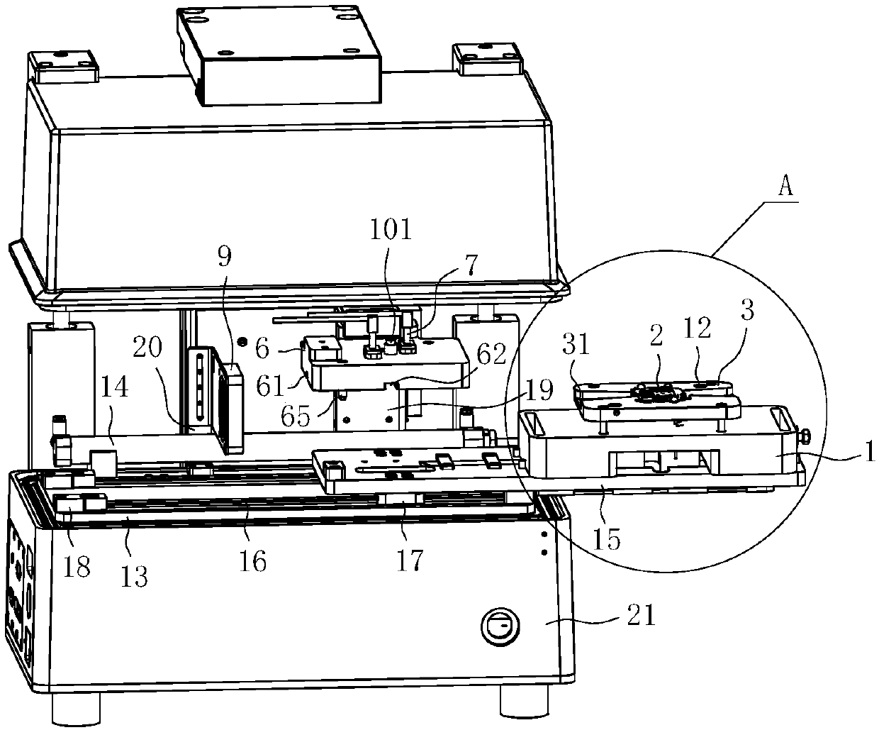
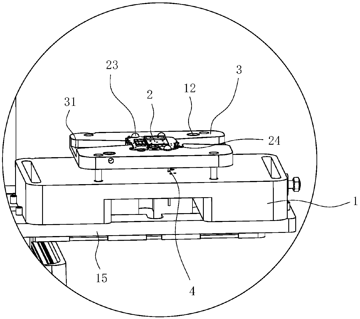
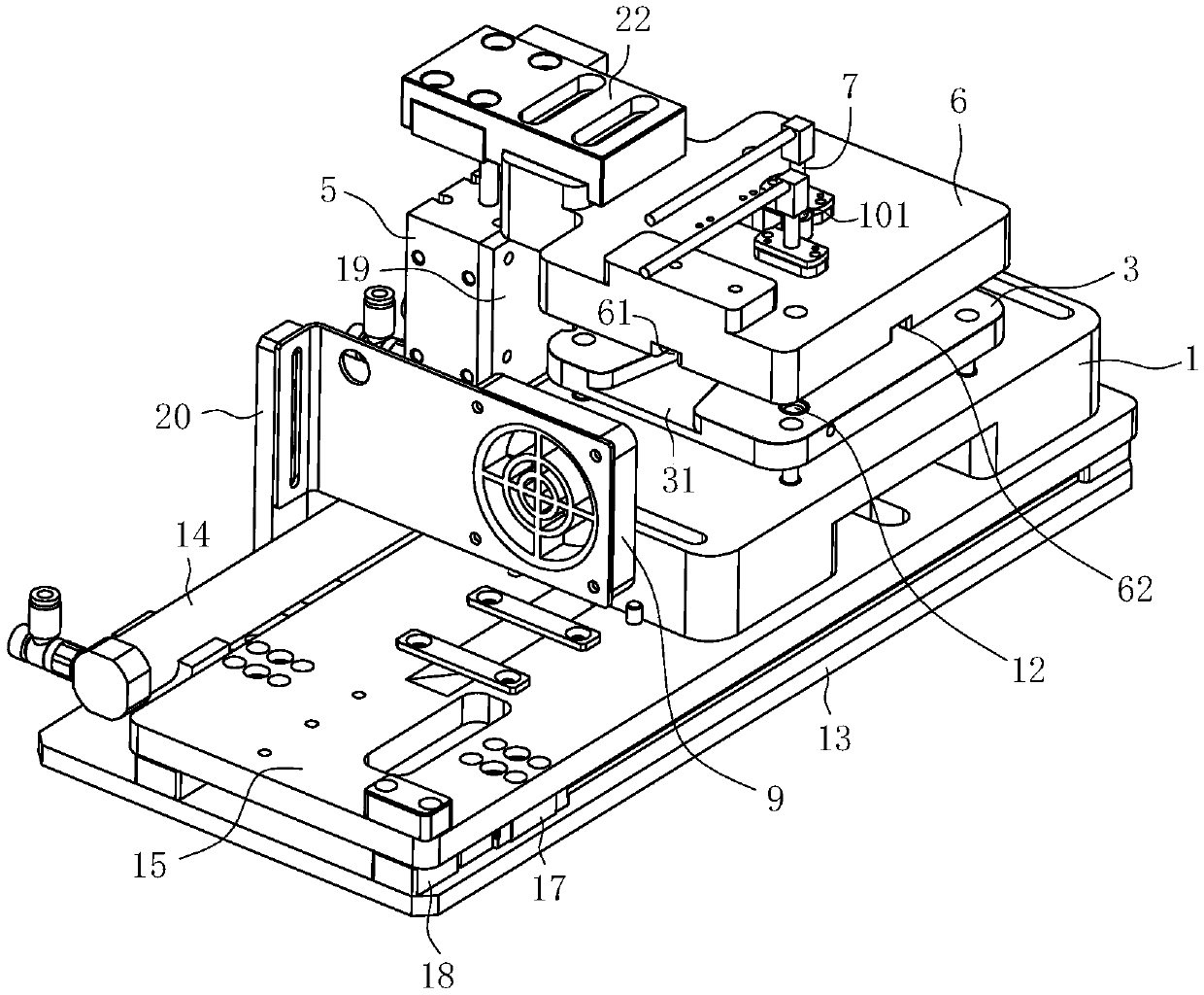
[0039] Such as Figure 2 to Figure 4Commonly shown, a radio frequency test device includes a test mechanism, the test mechanism includes a needle test module, the needle test module includes a probe base 1, and the upper side of the probe base 1 is fixedly provided with a positioning plate 3 for fixing the product, Probe base 1 is elastically floating with probe 4 electrically connected to testing equipment, and probe 4 passes through positioning plate 3 and is electrically connected to the lower test point of the product; The radio frequency needle base 6 used to compress the product is provided with a radio frequency needle 7 electrically connected to the test equipment. The radio frequency needle 7 passes through the radio frequency needle base 6 and is electrically connected to the upper test point of the product. The radio frequency needle base 6 corresponds to The position of the chip 2 of the product is provided with a horizontally extending upper air passage groove 61,...

Embodiment 2

[0049] Such as figure 1 As shown, a radio frequency test method includes the radio frequency test device described in Embodiment 1, and also includes a test step, and the test step includes:

[0050] S1, open the shielding box 21;

[0051] S2. Product push module movement: the second power device 14 drives the slide plate 15 to move laterally, and the slide plate 15 drives the probe holder 1 and the positioning plate 3 to move laterally to one side of the radio frequency needle base 6; place the product on the positioning plate 3 and Positioning, at this time, the probe 4 electrically connected to the test equipment on the probe base 6 passes through the positioning plate 3 and is electrically connected to the lower test point of the product; the second power unit 14 drives the slide plate 15 to move laterally, and the slide plate 15 drives the probe The base 1 and the positioning plate 3 move laterally to the bottom of the radio frequency needle base 6;

[0052] S3, close t...


PUM


Abstract

The invention discloses a radio frequency testing device and a radio frequency testing method, and relates to the technical field of radio frequency testing equipment. The testing device comprises a testing mechanism; the testing mechanism comprises a pricking pin testing module; an upper air channel groove extending transversely is formed in the position, corresponding to a chip of a product, ofa radio frequency pin base of the pricking pin testing module, and a lower air channel groove with the extending direction consistent with the extending direction of the upper air channel groove is formed in a positioning plate located below the product; one side of the upper air channel groove and one side of the lower air channel groove are provided with a fan blowing air in the extending direction of the upper air channel groove and the lower air channel groove. A guide groove is vertically formed in the position, corresponding to the chip, of the upper air channel groove; a heat dissipation copper block making contact with the chip is arranged in the guide groove in an elastic floating mode, and a first heat dissipation groove is formed in the end, making contact with the chip, of theheat dissipation copper block. The radio frequency testing device solves the problem about how to dissipate heat and reduce temperature of a chip in the radio frequency testing process, can complete the radio frequency testing of a product at one time, guarantees the accuracy of a radio frequency testing result, and reduces the testing cost.

Description

technical field [0001] The invention relates to the technical field of radio frequency testing equipment, in particular to a radio frequency testing device and a radio frequency testing method. Background technique [0002] Radio frequency refers to the electromagnetic frequency that can radiate into space, and the frequency range is from 300KHz to 300GHz. Radio frequency is referred to as RF, and radio frequency is radio frequency current, which is an abbreviation of high-frequency alternating electromagnetic waves. [0003] The shielding box is a shielding body of various shapes such as shells, plates, and sleeves made of conductive or magnetically conductive materials, which limits the electromagnetic capability within a certain space and is used to suppress radiation interference. A device that performs processing to provide a non-interfering test environment for the wireless communication device under test. [0004] In recent years, thanks to the promotion of various ...

Claims


Application Information

Patent Timeline
IPC IPC(8): G01R31/28H01L23/467
CPCG01R31/2808G01R31/2815H01L23/467
Inventor 高海燕魏云峰丁永胜景凯凯
Owner GOERTEK INC
Why Eureka
Try Eureka