Multi-branch jet flow microchannel chip liquid cooling and heat radiating device

A liquid-cooled heat dissipation, micro-channel technology, applied in the direction of semiconductor/solid-state device components, semiconductor devices, electrical components, etc., can solve the problems of increasing heat exchange efficiency, temperature rise, chip temperature deformation, etc., to improve the uniformity of heat dissipation The effect of increasing the heat exchange area and improving the heat dissipation capacity

Active Publication Date: 2019-03-26
HUAZHONG UNIV OF SCI & TECH
View PDF3 Cites 30 Cited by
  • Summary
  • Abstract
  • Description
  • Claims
  • Application Information

AI Technical Summary

Problems solved by technology

However, when the liquid flows in the microchannel, it will heat up, so that the heat dissipation capacity in the flow direction will gradually decrease, resulting in a gradual increase in the temperature of the heat source of the chip, and the inhomogeneity of the chip temperature will cause a series of reliable problems such as thermal stress and deformation of the material. sexual problems
The commonly used array nozzle jet cooling method can effectively solve the problem of uneven chip temperature distribution, but the fluid between multiple nozzles is prone to mutual interference, which affects the jet cooling effect and greatly weakens the heat dissipation capacity of jet cooling
[0004] Patent CN102014598B discloses a prism array jet microchannel radiator, which includes a prism array structure, a jet structure, an inlet and outlet crossing structure, a liquid separation structure, and a structure for arranging inlets and outlets. The prism array structure makes the cooling liquid turbulent and takes away The heat transferred from the matrix to the prismatic structure increases the heat exchange efficiency, but the inlet and outlet channels are too close together, which easily increases the temperature of the inlet liquid, and the prismatic structure cannot limit the flow direction, so that adjacent jets will still have a relatively high temperature. serious interaction

Method used


Image

  • Multi-branch jet flow microchannel chip liquid cooling and heat radiating device
  • Multi-branch jet flow microchannel chip liquid cooling and heat radiating device
  • Multi-branch jet flow microchannel chip liquid cooling and heat radiating device

Examples


Embodiment Construction

[0030] In order to make the object, technical solution and advantages of the present invention clearer, the present invention will be further described in detail below in conjunction with the accompanying drawings and embodiments. It should be understood that the specific embodiments described here are only used to explain the present invention, not to limit the present invention. In addition, the technical features involved in the various embodiments of the present invention described below can be combined with each other as long as they do not constitute a conflict with each other.

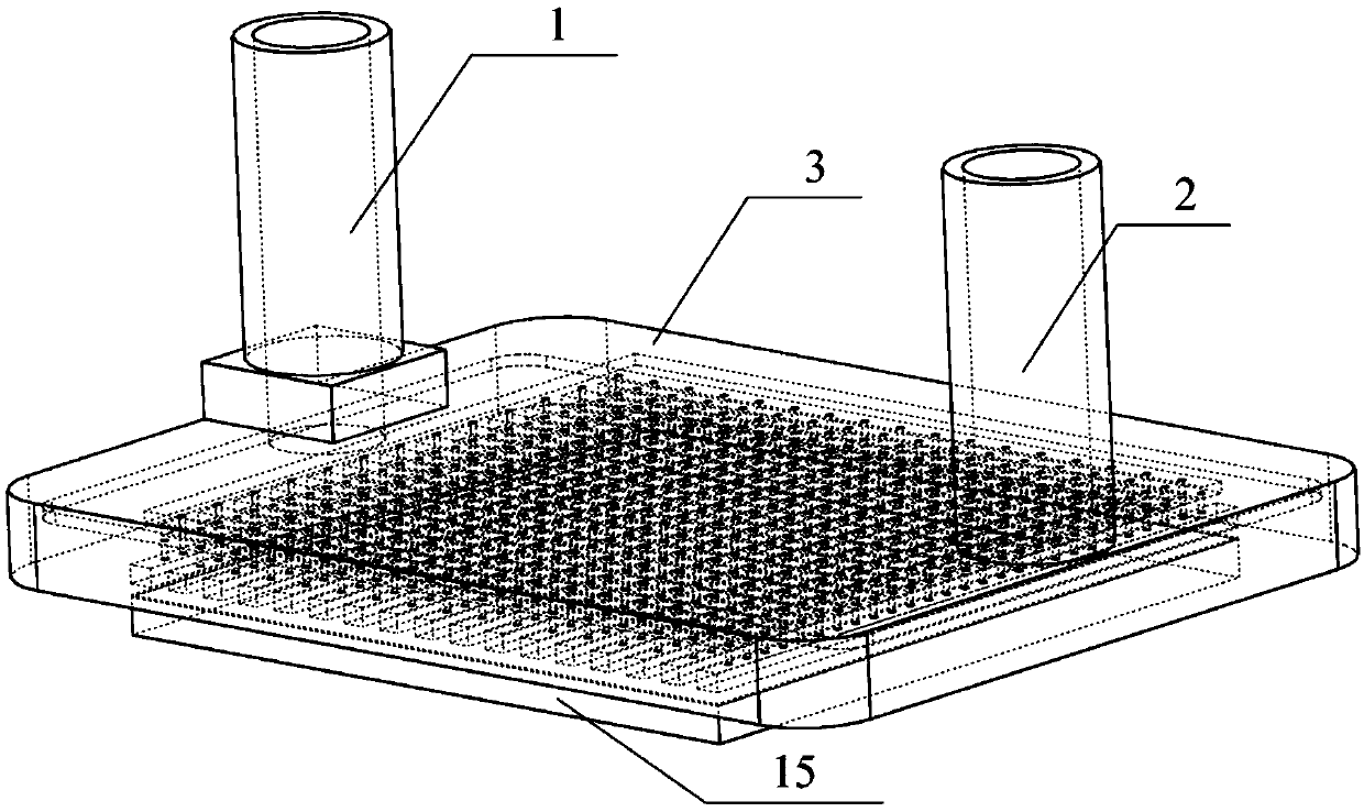
[0031] Such as figure 1 As shown, the embodiment of the present invention provides a liquid-cooled cooling device for a multi-jet microchannel chip, which includes a coolant inlet pipe 1, a coolant outlet pipe 2 and a multi-jet microchannel cavity 3, wherein the coolant The inlet pipe 1 and the cooling liquid outlet pipe 2 are installed on the multi-manifold jet microchannel cavity 3 for the in...


PUM


Abstract

The invention belongs to the field of the heat dissipation of electronic devices and specifically discloses a multi-branch jet flow microchannel chip liquid cooling and heat radiating device which comprises a cooling liquid inlet pipe, a cooling liquid outlet pipe and a multi-branch jet flow microchannel cavity. The cooling liquid inlet pipe and the cooling liquid outlet pipe are installed on themulti-branch jet flow microchannel cavity which is a compact whole body formed by stacking and bonding an inlet and outlet layer, a recovery layer, a recovery hole layer, a jet nozzle layer and a microchannel layer in order, the cooling liquid inlet pipe is arranged on the inlet and outlet layer and communicates with the jet nozzle layer, cooling liquid enters into the microchannel layer via the jet nozzle layer, the cooling liquid outlet pipe is arranged on the inlet and outlet layer and communicates with the recovery layer, and the heat-absorbing cooling liquid is discharged out of the cooling liquid outlet pipe from the microchannel layer via the jet nozzle layer, the recovery hole layer and the recovery layer. According to the multi-branch jet flow microchannel chip liquid cooling andheat radiating device, the uniformity of the temperature of a chip can be improved, the heat dissipation performance is improved, and the heat dissipation problems of a high heat flux density chip anda heat generating electronic device can be solved.

Description

technical field [0001] The invention belongs to the field of heat dissipation of electronic devices, and more specifically relates to a liquid-cooled heat dissipation device for a multi-firing microchannel chip. Background technique [0002] High temperature will cause great harm to the performance and reliability of electronic devices, and the failure rate of electronic devices will increase exponentially with the increase of temperature. A large amount of heat generated by electronic devices must be evacuated in time to ensure that the devices can work normally, efficiently and safely. With the rapid development of semiconductor technology and electronic technology, the integration of electronic devices has doubled, followed by increasing heat generation. For example, billions of heat-generating transistors are integrated in a millimeter-sized chip and connecting wires. Since the iterative development of heat dissipation technology is far behind the blowout development o...

Claims


Application Information

Patent Timeline
Patent Type & Authority Applications(China)
IPC IPC(8): H01L23/473
CPCH01L23/4735
Inventor 罗小兵吴睿康蓝威范义文邹浩
Owner HUAZHONG UNIV OF SCI & TECH
Why Eureka
Try Eureka