Single-station semi-automatic dynamic balance adjusting device

An adjustment device and semi-automatic technology, applied in the mechanical field, can solve problems such as rotor imbalance, safety accidents, wear, etc., and achieve the effects of reducing eccentricity, improving accuracy, and avoiding positioning deviation

Pending Publication Date: 2019-03-26
深圳至汉装备科技有限公司
View PDF10 Cites 5 Cited by
  • Summary
  • Abstract
  • Description
  • Claims
  • Application Information

AI Technical Summary

Problems solved by technology

However, in the actual design, manufacture and production, the mass distribution of the rotor may be asymmetric due to reasons such as substandard manufacturing process, design defects or uneven material, so that there is an imbalance in the rotor. When the rotor is running at high speed, this imbalance becomes more serious. Obviously, it will cause problems such as vibration, noise, wear and even safety accidents.
[0004] Therefore, before the rotor is rotated and assembled, it is necessary to perform a dynamic unbalance test on the rotor, and then mill the unbalanced point on the rotor or increase the weight of the unbalanced point according to the situation. However, the existing detection devices use direct fixing when detecting the rotor. The rotor is fixed in a fixed way, and the spatial position of the rotor cannot be adjusted; in addition, the existing rotor is directly driven by the motor shaft to rotate synchronously during the test. When measuring a heavy rotor in this way, its gravity on the motor shaft will affect the dynamic balance. measurement result

Method used


Image

  • Single-station semi-automatic dynamic balance adjusting device
  • Single-station semi-automatic dynamic balance adjusting device
  • Single-station semi-automatic dynamic balance adjusting device

Examples


Embodiment Construction

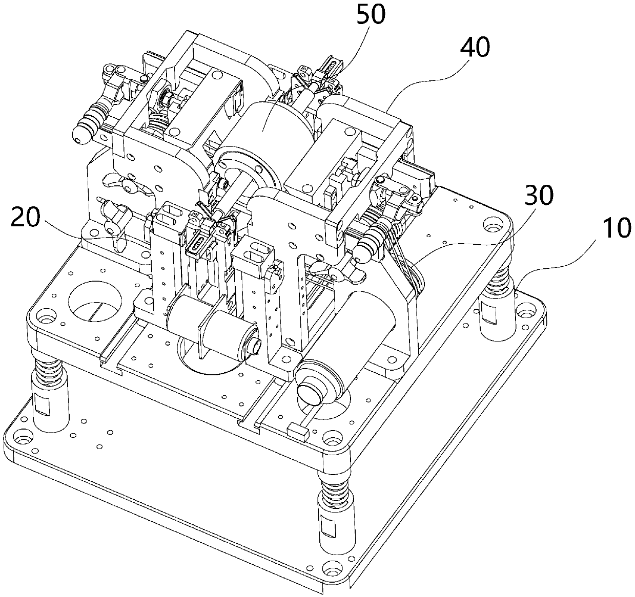
[0029] like Figure 1~6 As shown, one embodiment of the present invention discloses a single-station semi-automatic dynamic balance adjustment device, which generally includes: an elastic shock-absorbing seat 10 for eliminating external vibration interference, and an elastic shock-absorbing seat 10 installed on the elastic shock-absorbing seat 10 for supporting The supporting assembly 20 of the dynamically balanced rotor 50 to be tested, the driving assembly 30 for driving the rotor 50 to rotate, the rotor clamp 40 for clamping and fixing the rotor 50 for dynamic balance adjustment, and the control module for controlling the measurement process of the rotor 50 .

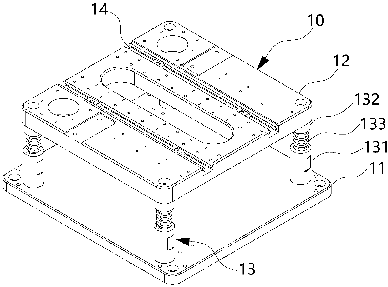
[0030] The elastic shock absorber 10 includes two fixed platforms 11 and 12 installed by superposing elastic parts 13. The fixed platforms 11 and 12 can reduce or eliminate the vibration of the ground through the elastic parts 13, so as to avoid transmission to the rotor 50 and affect the dynamic balance test effect. ...


PUM


Abstract

The invention provides a single-station semi-automatic dynamic balance adjusting device comprising an elastic shock-absorbing seat, a support assembly, a driving assembly, a rotor clamp, and a controlmodule. The elastic shock-absorbing seat is formed by two fixation platforms that are installed and laminated by an elastic member. The support assembly includes two support bases with adjustable vertical heights and horizontal positions. The driving assembly includes a motor, a wheel group with the adjustable tension degree, and a belt. The rotor clamp is used for clamping and fixing a tested rotor. The control module is used for controlling the measuring process of the rotor and receiving and processing data during the testing process to obtain an imbalance point of the rotor. Therefore, the external vibration can be reduced or isolated for rotor measurement; the rotor is supported by a non-fixed way to reduce the influence on the rotor rotation by the fixation force, so that the dynamic balancing precision is improved; and since the rotor is driven by the belt, the eccentric effect on the rotor is reduced by the direct motor connection. With the rotor clamp, the rotor is clamped and fixed directly after rotor testing completion, so that a problem of the imbalance point positioning deviation after rotor movement is solved.

Description

technical field [0001] The invention relates to the mechanical field, in particular to a single-station semi-automatic dynamic balance adjustment device capable of automatically detecting the balance state of a dynamically unbalanced rotor and clamping the detected rotor at the current position. Background technique [0002] Motor rotors are widely used in motors of electrical appliances, robots, drones and other equipment. As the automation level of household appliances and industrial manufacturing becomes higher and higher, the requirements for motors are also moving from low power and low speed in the past. Develop in the direction of high speed and high precision. [0003] When an ideal rotor rotates at a constant speed, due to its uniform mass distribution, the rotor's inertia axis and rotation axis coincide with each other, and no unbalanced centrifugal force will be generated. However, in the actual design, manufacture and production, the mass distribution of the rot...

Claims


Application Information

Patent Timeline
Patent Type & Authority Applications(China)
IPC IPC(8): H02K15/16
CPCH02K15/165
Inventor 蒙伟强毛乐山刘洋张秘
Owner 深圳至汉装备科技有限公司
Why Eureka
Try Eureka