
Iron plate grinding device convenient for removing scrap scraps

An iron plate and flat plate technology, applied in the field of iron plate grinding, can solve the problems of delayed iron plate processing time, increased labor intensity, and inconvenient waste cleaning, and achieves low cleaning labor intensity, low labor intensity, and avoids processing time. Effect

Inactive Publication Date: 2019-03-29
南京壹久软件科技有限公司
View PDF0 Cites 3 Cited by
  • Summary
  • Abstract
  • Description
  • Claims
  • Application Information

AI Technical Summary

Problems solved by technology

[0003] When grinding iron plates, a large amount of waste chips may be generated, and the waste chips may splash around with the rotating grinding disc. It is inconvenient to clean the waste chips, and the cleaning labor intensity is increased; when the grinding disc is used for a long time, it may be If there is wear and tear, the grinding disc may need to be replaced during processing, which may delay the processing time of the iron plate; after the iron plate is polished, it may be necessary to spray anti-rust oil on the iron plate for anti-rust treatment, generally by manual Spraying with a hand-held nozzle is labor-intensive

Method used


Image

  • Iron plate grinding device convenient for removing scrap scraps
  • Iron plate grinding device convenient for removing scrap scraps
  • Iron plate grinding device convenient for removing scrap scraps

Examples


Embodiment Construction

[0034] The following will clearly and completely describe the technical solutions in the embodiments of the present invention with reference to the accompanying drawings in the embodiments of the present invention. Obviously, the described embodiments are only some, not all, embodiments of the present invention. Based on the embodiments of the present invention, all other embodiments obtained by persons of ordinary skill in the art without making creative efforts belong to the protection scope of the present invention.

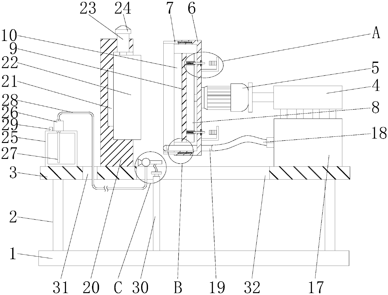
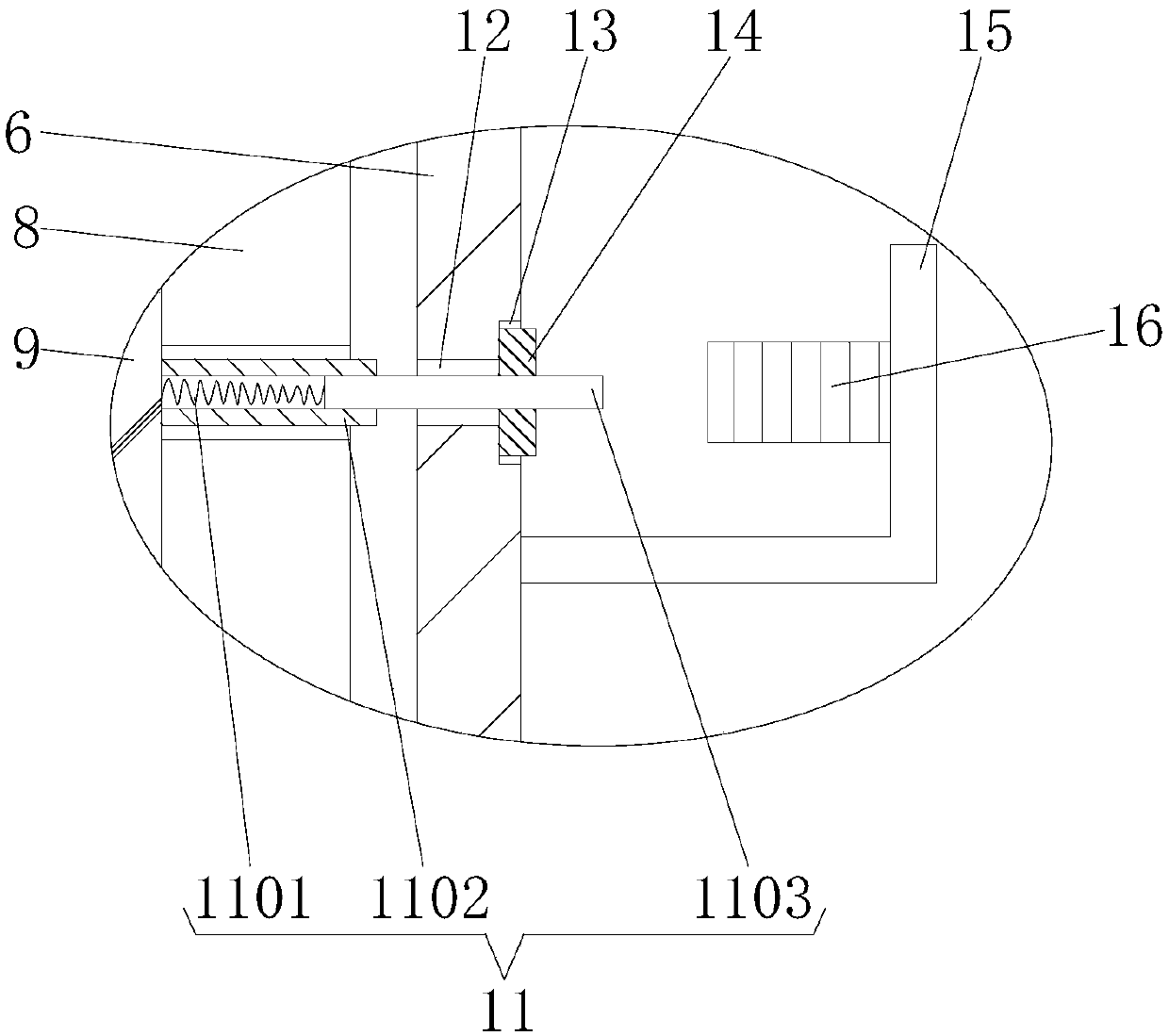
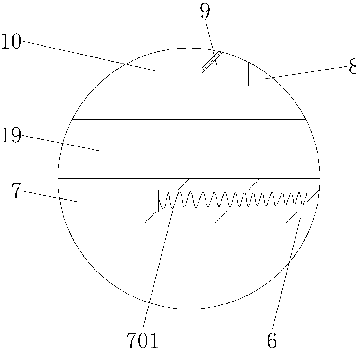
[0035] see Figure 1-9 As shown, an iron plate grinding device that facilitates waste removal includes a bottom plate 1, a flat plate 3, a grinding structure, a chip suction structure, and an antirust spraying structure. The top of the bottom plate 1 is fixed to the flat plate 3 through a support rod 2, and the bottom plate 1 and the plate 3 provide installation space for the electric push rod 30;

[0036] The grinding structure includes an electro-hydraulic ...


PUM


Abstract

The invention discloses an iron plate grinding device convenient for removing scrap scraps. The device comprises a bottom plate, a supporting rod, a flat plate, an electro-hydraulic push rod, a motor,a protective cover, a cylinder, a first spring, a disc, a mounting plate, a mounting bolt, a grinding disc, a telescopic rod, a second spring, a sleeve, an iron rod, a through hole, a clamping groove, a limiting strip, a square hole, a connecting rod, an electromagnet, an industrial dust collector, a straight pipe, a straight pipe, a suction hole, a sealing cap, a fixing block, a permanent magnet, an iron plate, a threaded barrel, a locking bolt, an oil tank, an oil well pump, an oil pumping pipe, an oil outlet hose, an oil filling port, an electric push rod, a first through groove, a secondthrough groove, a gooseneck pipe, a connecting plate, an oil distributing pipe and a nozzle. The device is reasonable in structure and novel in design, through the arrangement of the protective cover,the cylinder and the first spring, the grinding disc and the iron plate can be covered when the grinding machine is used for grinding, the generated scraps can be effectively removed through the chipsuction structure, so that the scraps generated by grinding can be prevented from splashing to the outside, and the cleaning labor intensity is low.

Description

technical field [0001] The invention relates to an iron plate grinding device, in particular to an iron plate grinding device which is convenient for waste removal, and belongs to the technical field of iron plate grinding applications. Background technique [0002] Iron plate is a commonly used processing material. It can be stamped through a stamping die to process different workpieces. During production and processing of iron plate, it needs to be polished to smooth the surface of the iron plate and provide convenience for subsequent processing. [0003] When grinding iron plates, a large amount of waste chips may be generated, and the waste chips may splash around with the rotating grinding disc. It is inconvenient to clean the waste chips and the labor intensity of cleaning is increased; when the grinding disc is used for a long time, it may be If there is wear and tear, the grinding disc may need to be replaced during processing, which may delay the processing time of ...

Claims


Application Information

Patent Timeline
Patent Type & Authority Applications(China)
IPC IPC(8): B24B7/07B24B47/12B24B55/06B24B45/00B24B55/04B05B9/04B05B13/04B05B15/68
CPCB24B7/07B05B9/0403B05B13/041B05B15/68B24B45/003B24B47/12B24B55/04B24B55/06
Inventor 赵裕杨宏图周同根
Owner 南京壹久软件科技有限公司
Learn More