Automobile engine connecting rod locating and machining equipment

A technology for automobile engines and processing equipment, applied in metal processing equipment, grinding/polishing equipment, manufacturing tools, etc., can solve the problems of inability to achieve rapid positioning of connecting rods, poor connecting rod rigidity, affecting processing accuracy, etc., and achieve positioning. Fast and effective clamping, reasonable structure setting, and the effect of improving work efficiency

Active Publication Date: 2019-03-29
阜南县申通机械制造有限公司
View PDF6 Cites 7 Cited by
  • Summary
  • Abstract
  • Description
  • Claims
  • Application Information

AI Technical Summary

Problems solved by technology

[0003] 1. Due to the poor rigidity of the connecting rod itself, special attention should be paid to the selection of positioning and clamping points. The existing connecting rod positioning devices usually only fix the big and small ends of the connecting rod, while ignoring the fixing of the rod body, which is easy to During the processing, the shaft is deformed to affect the processing accuracy;
[0004] 2. In the existing connecting rod positioning processing device, the installation of the positioning fixture for the connecting rod is relatively complicated, and the fast positioning of the connecting rod cannot be achieved, resulting in low work efficiency;
[0005] 3. The existing grinding processing device of the connecting rod usually cannot grind both sides of the connecting rod at the same time, and only one side of the connecting rod is processed, so that the rod body is easily deformed and the processing accuracy is affected, and the work efficiency is not high

Method used


Image

  • Automobile engine connecting rod locating and machining equipment
  • Automobile engine connecting rod locating and machining equipment
  • Automobile engine connecting rod locating and machining equipment

Examples


Embodiment Construction

[0025] The following will clearly and completely describe the technical solutions in the embodiments of the present invention with reference to the accompanying drawings in the embodiments of the present invention. Obviously, the described embodiments are only some of the embodiments of the present invention, not all of them. Based on the embodiments of the present invention, all other embodiments obtained by persons of ordinary skill in the art without making creative efforts belong to the protection scope of the present invention.

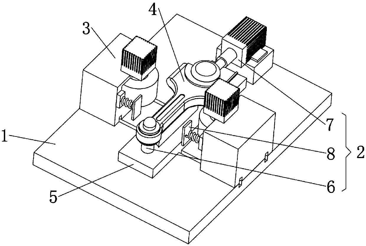
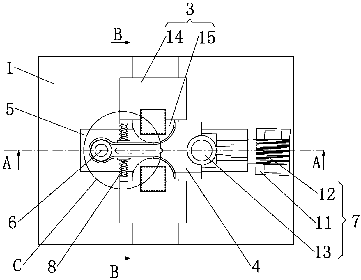
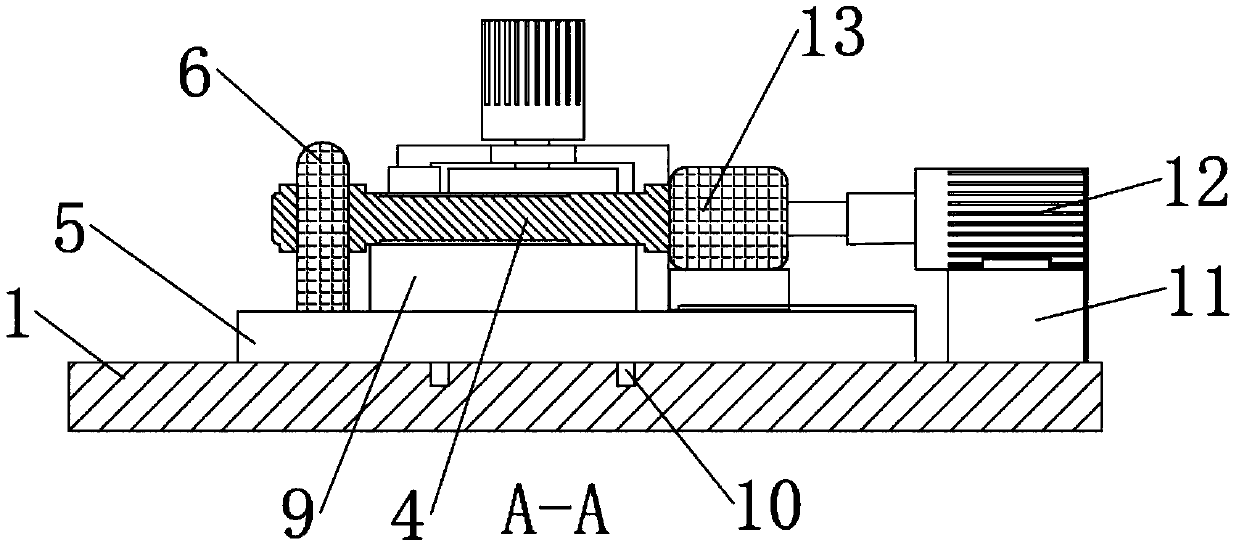
[0026] see Figure 1 to Figure 6 , the present invention provides a technical solution: an automotive engine connecting rod positioning processing equipment, including a processing table 1, a positioning mechanism 2 and a processing mechanism 3, such as figure 1 As shown, the upper surface of the processing table 1 is provided with a cuboid-shaped positioning support seat 5, and the upper surface of the positioning support seat 5 is provided with...


PUM


Abstract

The invention discloses automobile engine connecting rod locating and machining equipment. The automobile engine connecting rod locating and machining equipment comprises a machining table, a locatingmechanism and a machining mechanism. A locating support seat is arranged on the upper surface of the machining table. A connecting rod support seat is arranged on the upper surface of the locating support seat. The locating mechanism comprises a small-end fixing pillar, a large-end fixing device and a rod body fixing device. The large-end fixing device comprises a hydraulic machine support seat,a hydraulic machine and a large-end fixing pillar. A connecting rod is arranged on the upper surface of the connecting rod support seat. The machining mechanism comprises a grinding wheel seat and a grinding wheel. According to the automobile engine connecting rod locating and machining equipment, a small end of the connecting rod is arranged outside the small-end fixing pillar in a sleeving manner, and the large-end fixing pillar is controlled to be in close contact with a large end of the connecting rod through the hydraulic machine, so that the connecting rod is fixed preliminarily; the rodbody fixing device is arranged at the left side of the grinding wheel seat; when the grinding wheel seat moves toward the inner side, two pressing plates are in contact with the two sides of a rod body of the connecting rod and gradually clamp, and the rod body of the connecting rod is prevented from shifting in the machining process; and locating and clamping are conducted fast and effectively.

Description

technical field [0001] The invention relates to the technical field of auto parts processing, in particular to an automotive engine connecting rod positioning processing equipment. Background technique [0002] The connecting rod is one of the five major parts of the engine and an important safety part of the engine. The quality of the connecting rod directly affects the usability and safety of the engine. The engine connecting rod is mainly composed of three parts: the piston pin hole end (small end), the crankshaft pin hole end (big end) and the shaft. In the machining process of the engine connecting rod, it is necessary to grind and chamfer the outside of the big and small ends of the connecting rod and clean the burrs. During the processing, the connecting rod needs to be positioned and processed to improve the processing accuracy. In actual use, the following disadvantages still exist: [0003] 1. Due to the poor rigidity of the connecting rod itself, special attent...

Claims


Application Information

Patent Timeline
Patent Type & Authority Applications(China)
IPC IPC(8): B24B9/04B24B27/00B24B41/06B24B41/02
CPCB24B9/04B24B27/0076B24B41/02B24B41/06
Inventor 顾叶闰
Owner 阜南县申通机械制造有限公司
Why Eureka
Try Eureka