Optical lens and imaging equipment

A technology of optical lens and optical imaging lens, which is applied in the field of optical imaging to achieve the effect of eliminating aberration and eliminating achromatic aberration

Active Publication Date: 2019-03-29
JIANGXI LIANCHUANG ELECTRONICS CO LTD
View PDF18 Cites 23 Cited by
  • Summary
  • Abstract
  • Description
  • Claims
  • Application Information

AI Technical Summary

Problems solved by technology

[0002] Optical lenses are usually composed of several lenses and are widely used in various aspects of social life. Taking into account high performance and low manufacturing cost has always been the goal of product development. However, the current optical lenses still cannot meet the requirements. Therefore, it is urgent to propose An optical lens that combines high performance with low manufacturing cost

Method used


Image

  • Optical lens and imaging equipment
  • Optical lens and imaging equipment
  • Optical lens and imaging equipment

Examples


no. 1 example

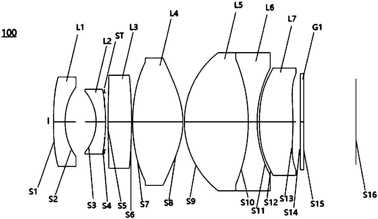
[0071] see figure 1 , an optical lens 100 provided by the first embodiment of the present invention includes in sequence from the object side to the imaging surface: a first lens L1, a second lens L2, a stop ST, a third lens L3, a fourth lens L4, and a fifth lens L5, sixth lens L6, seventh lens L7, filter G1.

[0072] The first lens L1 has negative refractive power, the object side S1 is convex, and the image side S2 is concave. The first lens L1 is a glass aspherical lens. In other embodiments of the present invention, the first lens L1 may be a glass spherical lens.

[0073] The second lens L2 has negative refractive power, the object side S3 is concave, and the image side S4 is convex, and the second lens L2 is a glass spherical lens.

[0074] The third lens L3 has positive refractive power and both the object side S5 and the image side S6 are convex, and the third lens L3 is a glass spherical lens.

[0075] The fourth lens L4 has positive refractive power and both the o...

no. 2 example

[0088] see Figure 5 , shows a structural diagram of an optical lens 200 provided in this embodiment. The optical lens 200 among the present embodiment is roughly the same as the optical lens 100 among the first embodiment, the difference is that the image side S6 of the third lens L3 of the optical lens 200 among the present embodiment is a concave surface, and the seventh lens The object side S12 of L7 is concave, and the image side S13 is convex, and the radius of curvature and material selection of each lens are different. For specific parameters of each lens, see Table 2-1.

[0089] table 2-1

[0090]

[0091]

[0092] The parameters of each lens aspheric surface in this embodiment are shown in Table 2-2.

[0093] Table 2-2

[0094]

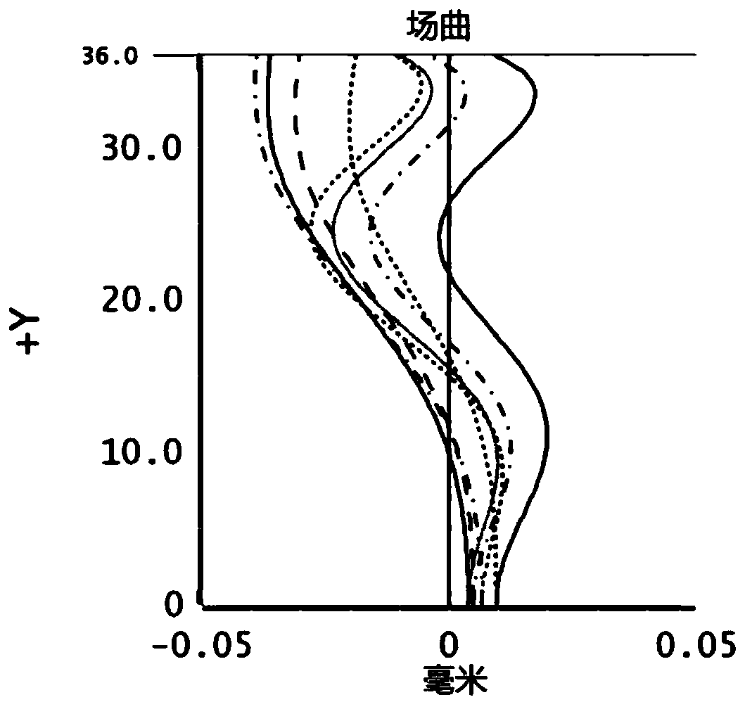
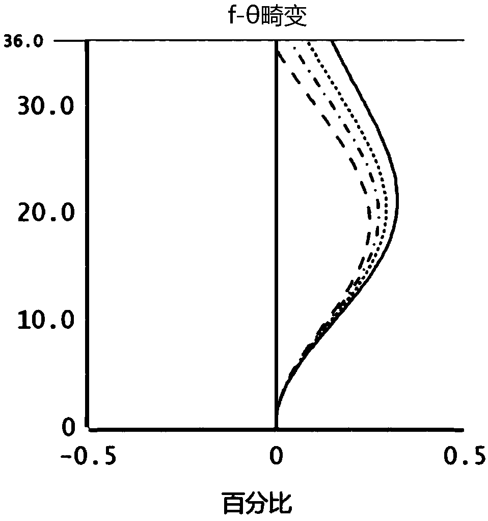
[0095] In this embodiment, its field curvature, distortion and axial chromatic aberration are as follows Figure 6 , Figure 7 and Figure 8 shown. Depend on Figure 6 to Figure 8 It can be seen that the field curvature, dis...

no. 3 example

[0097] see Figure 9 , shows a structural diagram of an optical lens 300 provided in this embodiment. The optical lens 300 among the present embodiment is roughly the same as the optical lens 100 among the first embodiment, the difference is that the third lens L3 of the optical lens 300 among the present embodiment is a glass aspheric lens, and the fourth lens L4 is Glass spherical lenses, as well as the radius of curvature and material selection of each lens are different. For the specific parameters of each lens, see Table 3-1.

[0098] Table 3-1

[0099]

[0100]

[0101] The parameters of each lens aspheric surface in this embodiment are shown in Table 3-2.

[0102] Table 3-2

[0103]

[0104] In this embodiment, its field curvature, distortion and axial chromatic aberration are as follows Figure 10 , Figure 11 and Figure 12 shown. Depend on Figure 10 to Figure 12 It can be seen that the field curvature, distortion, and chromatic aberration can be wel...


PUM


Abstract

The invention provides an optical lens which comprises the following components that are successively arranged from an object side to an imaging surface: a first lens which has negative focal power and an object-side surface that is a convex surface and an image-side surface that is a recessed surface; a second lens which has negative focal power and an object-side surface that is a recessed surface; a third lens which has positive focal power and an object-side surface that is a convex surface; a fourth lens with positive focal power; a fifth lens which has positive focal power and an object-side surface and an image-side surface that are convex surfaces; a sixth lens which has negative focal power and an object-side surface and an image-side surface that are recessed surfaces; wherein the fifth lens and the sixth lens are adhered for obtaining a adhering member; and a seventh lens with positive focal power, wherein the optical lens further comprises a diaphragm between the second lens and the third lens. The optical lens provided by the invention at least has a wide-spectrum imaging function. The invention further provides imaging equipment.

Description

technical field [0001] The invention relates to the technical field of optical imaging, in particular to an optical lens and imaging equipment. Background technique [0002] Optical lenses are usually composed of several lenses and are widely used in various aspects of social life. Taking into account high performance and low manufacturing cost has always been the goal of product development. However, the current optical lenses still cannot meet the requirements. Therefore, it is urgent to propose An optical lens that combines high performance with low manufacturing cost. Contents of the invention [0003] Based on this, the object of the present invention is to provide an optical lens and an imaging device to solve the above problems. [0004] In a first aspect, the present invention provides an optical lens, which comprises sequentially from the object side to the imaging surface: a first lens with negative refractive power and a convex surface on the object side surfac...

Claims


Application Information

Patent Timeline
Patent Type & Authority Applications(China)
IPC IPC(8): G02B13/00G02B13/18
CPCG02B13/0015G02B13/0045G02B13/006G02B7/028G02B9/62B60R11/04G02B9/64H04N23/51H04N23/55
Inventor 魏文哲刘绪明曾吉勇
Owner JIANGXI LIANCHUANG ELECTRONICS CO LTD
Why Eureka
Try Eureka