
Deadbeat direct torque control method for switched reluctance motor

A technology of direct torque control and switched reluctance motor, which is applied in motor generator control, AC motor control, electronic commutation motor control, etc. It can solve the problems of error, torque ripple not minimized, etc., and improve accuracy , good sudden change response ability, and the effect of reducing torque ripple and loss

Active Publication Date: 2019-03-29
DALIAN MARITIME UNIVERSITY
View PDF4 Cites 5 Cited by
  • Summary
  • Abstract
  • Description
  • Claims
  • Application Information

AI Technical Summary

Problems solved by technology

Although torque is used as a direct control variable in DTC, the torque ripple is not minimized, and since DTC uses Bang-Bang control, there is an inevitable error

Method used


Image

  • Deadbeat direct torque control method for switched reluctance motor
  • Deadbeat direct torque control method for switched reluctance motor
  • Deadbeat direct torque control method for switched reluctance motor

Examples


Embodiment Construction

[0056] In order to enable those skilled in the art to better understand the solutions of the present invention, the following will clearly and completely describe the technical solutions in the embodiments of the present invention in conjunction with the drawings in the embodiments of the present invention. Obviously, the described embodiments are only It is an embodiment of a part of the present invention, but not all embodiments. Based on the embodiments of the present invention, all other embodiments obtained by persons of ordinary skill in the art without making creative efforts shall fall within the protection scope of the present invention.

[0057] It should be noted that the terms "first" and "second" in the description and claims of the present invention and the above drawings are used to distinguish similar objects, but not necessarily used to describe a specific sequence or sequence. It is to be understood that the data so used are interchangeable under appropriate ...


PUM


Abstract

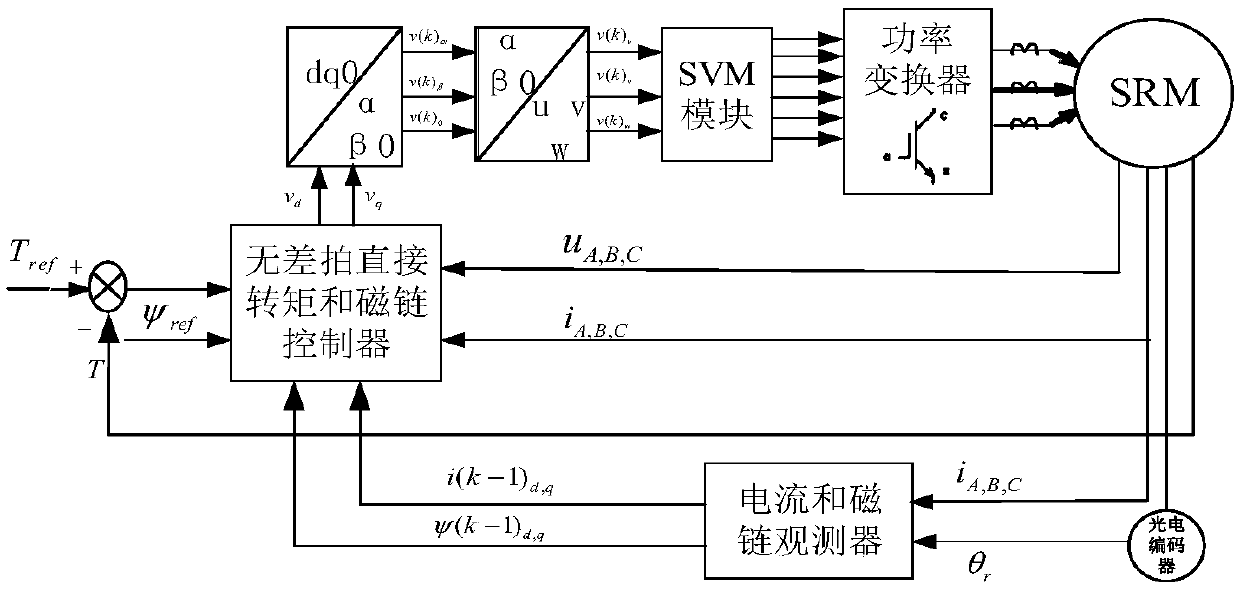
The invention provides a deadbeat direct torque control method for a switched reluctance motor. The deadbeat direct torque control method comprises the following steps: calculating a position angle ofa rotor by a photoelectric encoder and calculating a magnetic flux and current of a motor in a rotating coordinate system; giving a flux linkage and three-phase voltages and currents under the statorcoordinate system according to a difference between a given torque and a feedback torque; calculating a space voltage vector for controlling running of the motor in the rotating coordinate system ina next beat; and acquiring six-path pulse signals to control the motor. According to the invention, the torque and the flux linkage are controlled directly by controlling two-phase reference voltagesin the rotating reference coordinate system; and the torque and the flux linkage are controlled within one control cycle, so that the torque pulsation and the flux linkage are reduced substantially.

Description

technical field [0001] The invention relates to a torque control method of a switched reluctance motor, in particular to a stepless direct torque control method of a switched reluctance motor. Background technique [0002] Switched reluctance motor (SRM) was first proposed in the 1940s, but due to technical limitations at that time, it was not well developed. With the development of power electronic devices and the advantages of simple structure, low cost, good fault tolerance and wide speed range of the switched reluctance motor itself, it has attracted widespread attention from academia and industry, and a large number of researches have also been carried out. . Various specifications of switched reluctance motor speed control systems have been put into the market one after another, and the products cover electric vehicles, household appliances and other fields, which shows the broad application prospects of switched reluctance motors. However, the doubly salient pole st...

Claims


Application Information

Patent Timeline
Patent Type & Authority Applications(China)
IPC IPC(8): H02P25/08H02P25/098H02P21/00H02P21/05
CPCH02P21/0003H02P21/05H02P25/08H02P25/098
Inventor 许爱德张文韩乐乐任萍商超亿
Owner DALIAN MARITIME UNIVERSITY
Learn More