Microwave photon delay time measurement calibration device

A calibration device and microwave photon technology, applied in the field of optical measurement, can solve the problems of not being able to give the measurement accuracy of optical delay, lack of calibration scheme, etc.

Active Publication Date: 2019-03-29
ZHEJIANG UNIV
View PDF5 Cites 11 Cited by
  • Summary
  • Abstract
  • Description
  • Claims
  • Application Information

AI Technical Summary

Problems solved by technology

However, the traditional OFDR-based delay measurement system lacks a calibration scheme, and cannot give the accuracy of optical delay measurement under different time scales.

Method used


Image

  • Microwave photon delay time measurement calibration device
  • Microwave photon delay time measurement calibration device
  • Microwave photon delay time measurement calibration device

Examples


Embodiment Construction

[0025] In order to describe the present invention more specifically, the technical solutions of the present invention will be described in detail below in conjunction with the accompanying drawings and specific embodiments.

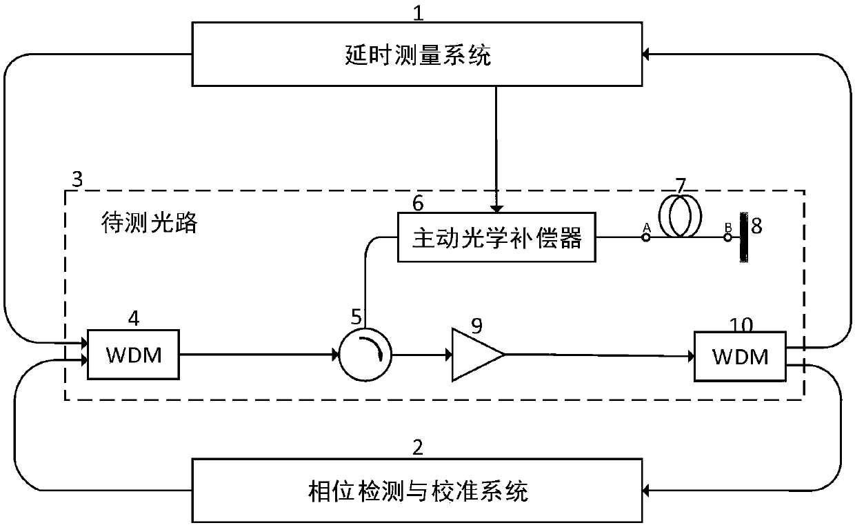
[0026] like figure 1 As shown, the microwave photon delay measurement and calibration device of the present invention includes three parts: a delay measurement system 1, a phase detection and calibration system 2, and an optical path to be measured 3; the optical path to be measured includes wavelength division multiplexers 4 and 10, and a circulator 5 , an active optical compensator 6, an optical fiber interface to be tested 7, a Faraday rotating mirror 8 and an optical amplifier 9; The optical signals are combined to the same test optical path, after passing through the circulator 5, they are connected to the active optical compensator 6, followed by the optical fiber interface 7 to be tested, and then connected to the Faraday rotating mirror 8, and the...


PUM


Abstract

The invention provides a microwave photon delay time measurement calibration device. The device includes three parts of a delay time measurement system, a phase detection calibration system and a to-be-measured optical path. A set of single-frequency signals generated by a signal generator inside the phase detection calibration system can select and use other multiple different frequency points, all the frequency points satisfy certain multiple relationships, and microwave photon link delay time is calibrated through detecting differential phases of all the frequency points between a referenceoptical link and the measured optical link and phase quantization. The device of the invention eliminates the 360-degree phase ambiguity problem in phase measurement on a principle scheme, can realize accurate calibration on a high-precision optical delay time quantity measurement device by using a highly stable hydrogen clock and an optical delay model, and can use more standard frequency signals for larger delay time quantity measurement.

Description

technical field [0001] The invention belongs to the technical field of optical measurement, and in particular relates to a microwave photon delay measurement calibration device. Background technique [0002] As an important application of microwave photonic technology, fiber delay lines have the advantages of small size, light weight, wide bandwidth, low loss, and strong anti-interference ability compared with traditional electrical delays, and are gradually applied to radar systems and electronic countermeasure systems. For example, the application of optical fiber delay line in traditional phase interferometer, the use of optical fiber delay line to delay the signals received by different antennas, so that the system can process various signals in time division, can effectively solve the problem of traditional phase interferometer with large amount of equipment and complicated system This is also a hot issue in the field of phase interferometer research. [0003] Optical ...

Claims


Application Information

Patent Timeline
Patent Type & Authority Applications(China)
IPC IPC(8): H04B10/079H04B10/61H04B10/071
CPCH04B10/071H04B10/0795H04B10/6164
Inventor 金晓峰秦东林杜一杰金向东余显斌谭庆景王国永
Owner ZHEJIANG UNIV
Why Eureka
Try Eureka