
Cylinder rod core production equipment and production method

A production equipment and rod core technology, applied in the field of cylinder rod core production equipment, can solve problems such as poor quality, low efficiency, waste of labor, etc., to achieve the effects of ensuring orderly work, increasing production capacity, and reducing production costs

Active Publication Date: 2019-04-02
ANHUI LAITE GAS SPRING CO LTD
View PDF7 Cites 4 Cited by
  • Summary
  • Abstract
  • Description
  • Claims
  • Application Information

AI Technical Summary

Problems solved by technology

[0006] Aiming at the problems of low production efficiency and poor quality of existing cylinder cores, the present invention provides a production equipment and production method for cylinder cores; it can effectively solve the problems of low efficiency, poor quality, and waste in the installation process of cylinder core products. Manual problems can improve the efficiency of product processing and assembly, and improve product quality

Method used


Image

  • Cylinder rod core production equipment and production method
  • Cylinder rod core production equipment and production method
  • Cylinder rod core production equipment and production method

Examples


Embodiment 1

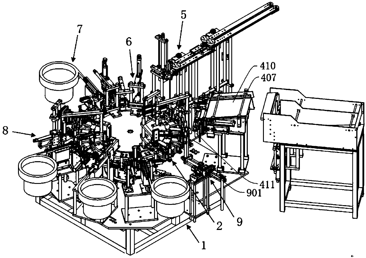
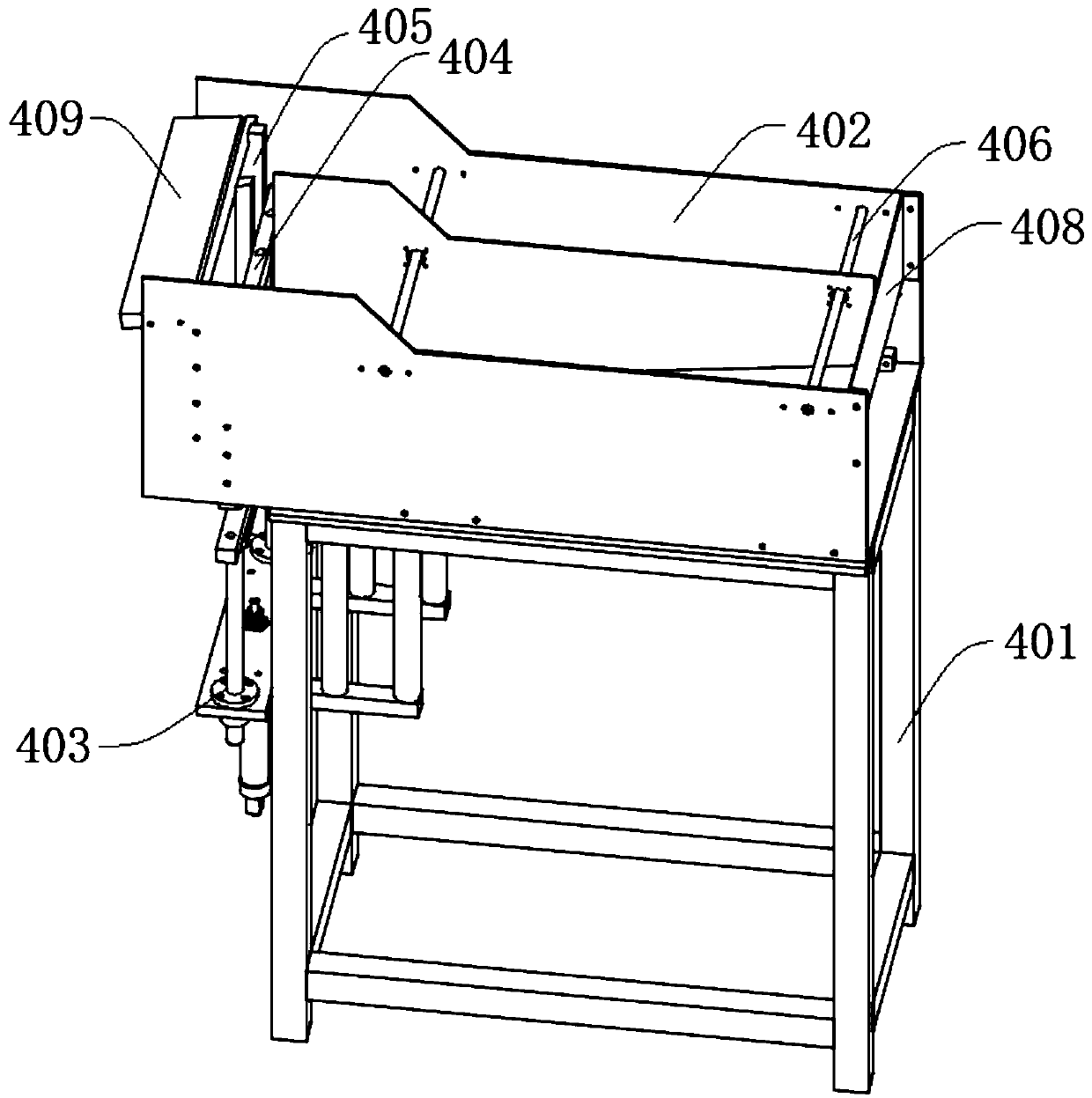
[0064] Such as figure 1 and image 3 As shown, a cylinder inner tube feeding device (or called an inner tube feeder) of this embodiment includes a base 1, a first support frame 401, a first storage box 402, a first cylinder 403, a first upper The push rod 404 , the first push slot 405 , the first limiting rod 406 , the second limiting rod 407 , the first limiting plate 408 , the inclined plate 409 and the first feeding platform 410 .

[0065] The first feeding platform 410 is connected to the base 1, the first support frame 401 is located on one side of the base 1, the first material storage box 402 is installed on the first support frame 401, and the first cylinder 403 is installed on one side of the support frame , located on the lower side of the first material storage box 402, the first cylinder 403 is connected with the first upper push rod 404, the first upper push rod 404 is located inside one side of the material storage box, and the first feeding platform 410 is loca...

Embodiment 2

[0073] On the basis of Embodiment 1, this embodiment provides a cylinder rod core production equipment.

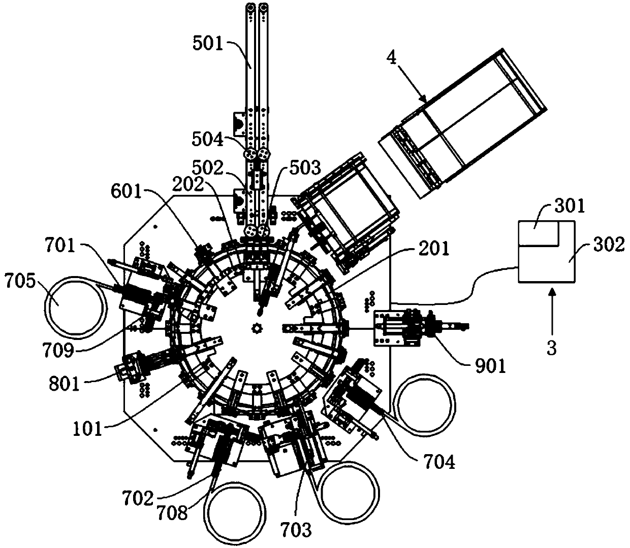
[0074] Such as Figure 1-4 As shown, a cylinder rod core production equipment in this embodiment includes a base 1, a turntable dividing mechanism 2, an electrical control system 3, an inner tube automatic feeding and placement mechanism 4, a piston rod automatic feeding and installation mechanism 5, a pressing Piston rod and refueling mechanism 6, automatic feeding and assembly mechanism 7, turning mechanism 8.

[0075] The base 1 serves as the installation basis of the entire device, providing a support base for all components, and ensuring the continuous and effective work of each component on the base 1 . And the base 1 is provided with a sensor 101 inside each workpiece clamping area along the stationary dividing disk 201. The sensor 101 is used to detect the state of the workpiece clamped by the dividing disk 201, and feed back the detected result information to the...

Embodiment 3

[0085] This embodiment provides a production method of a cylinder rod core production equipment according to a kind of cylinder rod core production equipment in embodiment 2, comprising the following steps:

[0086] S1. Raw material preparation, put the inner tube into the material storage box of the inner tube automatic feeding and placement mechanism 4, place the piston rod on the first conveyor belt 501 of the piston rod automatic feeding and installation mechanism 5, and place the piston rod to the control box surrounding the base 1 in turn. Valve automatic feeding and assembly mechanism 701, leather bowl automatic feeding and assembly mechanism 702, bowl pad automatic feeding and assembly mechanism 703, and rear top set automatic feeding and assembly mechanism 704. and the rear top cover.

[0087] S2. Turn on the power, the motor starts to rotate, the inner tube automatic feeding and placement mechanism 4 starts feeding, the first cylinder 403 pushes the first upper push ...


PUM


Abstract

The invention discloses air cylinder rod core production equipment and a production method, and belongs to the field of air cylinder rod core machining. The equipment comprises a base, a turntable segmentation mechanism and an electrical control system, wherein the turntable segmentation mechanism and the electrical control system are installed on the base, and the turntable segmentation mechanismis electrically connected to the electrical control system; and the equipment further comprises an inner pipe automatic feeding and placing mechanism, a piston rod automatic feeding and installing mechanism, a downward pressing piston rod and oil adding mechanism, an automatic feeding and assembling mechanism and an overturning mechanism, wherein the inner pipe automatic feeding and placing mechanism, the piston rod automatic feeding and installing mechanism, the downward pressing piston rod and oil adding mechanism,the automatic feeding and assembling mechanism and the overturning mechanismare electrically connected to the electrical control system. According to the production equipment and the production method, the problems of low efficiency, poor quality and waste of labor in the installation process of the cylinder rod core product can be effectively solved, the product processing and assembling efficiency can be improved, the product quality can be improved, the equipment structure is simple, the design is reasonable, and the equipment is convenient to use.

Description

technical field [0001] The invention belongs to the technical field of cylinder rod core processing, and more specifically relates to a production equipment and production method of a cylinder rod core. Background technique [0002] The gas spring is also called the cylinder. In the prior art, the assembly of the components of the cylinder rod core is done manually; the manual assembly of the cylinder rod core is greatly affected by the proficiency of the personnel and the external environment. In the actual production process, the installation efficiency of a new employee is about 100 per hour, and the installation efficiency of a skilled employee is only about 120 per hour; the installation efficiency is relatively low. If the working season is winter, it is affected by temperature and Due to the influence of weather, the installation efficiency of employees will be lower. Not only that, but when employees install manually, it is easy to miss the installation, which makes...

Claims


Application Information

Patent Timeline
Patent Type & Authority Applications(China)
IPC IPC(8): B23P21/00
CPCB23P21/006Y02E30/30
Inventor 陶声荣
Owner ANHUI LAITE GAS SPRING CO LTD
Learn More