Cooling control system, cooling control method, cooling controller and electric automobile

A technology of cooling control and controller, which is applied in the direction of electric power unit, arrangement of cooling combination of power unit, power unit, etc., can solve the problems of high energy consumption and low cooling efficiency, achieve low energy consumption, good energy saving effect, The effect of high cooling efficiency

Inactive Publication Date: 2019-04-02
ZHEJIANG PANGOOD POWER TECH CO LTD
View PDF6 Cites 12 Cited by
  • Summary
  • Abstract
  • Description
  • Claims
  • Application Information

AI Technical Summary

Problems solved by technology

[0003] In the prior art, the flow rate of the water pump on the cooling pipeline is constant, and the rotation speed of the fan is generally constant, which has the problems of low cooling efficiency and high energy consumption

Method used


Image

  • Cooling control system, cooling control method, cooling controller and electric automobile
  • Cooling control system, cooling control method, cooling controller and electric automobile
  • Cooling control system, cooling control method, cooling controller and electric automobile

Examples


Embodiment Construction

[0058] The invention discloses a cooling control system, a cooling control method, a cooling controller and an electric vehicle, which can improve the cooling efficiency of the driving motor and the motor controller, and have low energy consumption.

[0059] The following will clearly and completely describe the technical solutions in the embodiments of the present invention with reference to the accompanying drawings in the embodiments of the present invention. Obviously, the described embodiments are only some, not all, embodiments of the present invention. Based on the embodiments of the present invention, all other embodiments obtained by persons of ordinary skill in the art without making creative efforts belong to the protection scope of the present invention.

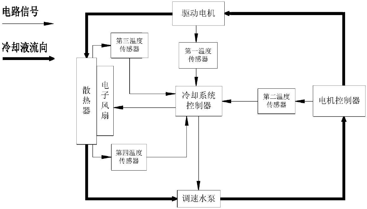
[0060] see figure 1 , figure 1 The schematic diagram of the cooling control system provided by the embodiment of the present invention.

[0061] The cooling control system provided by the embodiment of the pres...


PUM


Abstract

The invention discloses a cooling control system, a cooling control method, a cooling controller and an electric automobile. The cooling control system comprises a cooling pipeline, a heat radiator, an electronic fan, a first temperature sensor, a second temperature sensor, a third temperature sensor, a fourth temperature sensor and a cooling controller, wherein the cooling pipe is used for conveying a cooling fluid to pass through a speed regulating water pump, a motor controller, a driving motor and the heat radiator in sequence and enabling the cooling fluid to flow in circulation; the heatradiator is used for cooling the cooling fluid; the electronic fan is used for ventilation of the heat radiator; the first temperature sensor is used for measuring a temperature of the driving motor;the second temperature sensor is used for measuring a temperature of the motor controller; the third temperature sensor is used for measuring the temperature of the cooling fluid in an inlet of the heat radiator; the fourth temperature sensor is used for measuring the temperature of the cooling fluid in an outlet of the heat radiator; the cooling controller is independently arranged relative to avehicle control unit; an input end of the cooling controller is used for receiving temperature signals of the four temperature sensors; and an output end of the cooling controller is connected with the electronic fan and the speed regulating water pump. According to the cooling control system, the cooling control method, the cooling controller and the electric automobile, the cooling efficiency of the driving motor and the cooling efficiency of the motor controller can be enhanced, and the energy consumption is low.

Description

technical field [0001] The invention relates to the technical field of automobiles, in particular to a cooling control system and a cooling control method, a cooling controller and an electric vehicle. Background technique [0002] The parts that need to be liquid-cooled in the whole electric vehicle include the driving motor and the motor controller. In order to ensure that the driving motor and the motor controller work at an appropriate temperature, a cooling control system is generally used to dissipate heat from the cooling pipeline flowing through the driving motor and the motor controller. The cooling control system includes a radiator arranged on the cooling pipeline and a fan for ventilating the radiator. [0003] In the prior art, the flow rate of the water pump on the cooling pipeline is constant, and the rotation speed of the fan is generally constant, which has the problems of low cooling efficiency and high energy consumption. [0004] Therefore, how to impro...

Claims


Application Information

Patent Timeline
Patent Type & Authority Applications(China)
IPC IPC(8): B60K1/00B60K11/04B60K11/06
CPCB60K1/00B60K11/04B60K11/06B60K2001/006
Inventor 梁卫刚闫志朋
Owner ZHEJIANG PANGOOD POWER TECH CO LTD
Why Eureka
Try Eureka